Getting into SHAPE: Best Practices for Audio Flowgraph Construction
Introduction
The scalable hardware audio processing engine (SHAPE) provides hardware acceleration for a number of the most common building blocks of audio playback and manipulation.
A title is in full control of the configuration and ordering of SHAPE processing blocks, which the audio control processor (ACP)—a hardware component—manages. The title creates defined paths to chain together one or more SHAPE components from input to output. These paths are known as flowgraphs. Once created, each flowgraph is submitted as a series of commands for the ACP to process.
This paper discusses the best practices for creating and submitting flowgraphs. Specifically, this paper discusses flowgraphs that successfully implement the runtime scenarios that you will encounter most frequently, as well as configurations that you should avoid in order to maximize performance.
In this topic:
- SHAPE components and capabilities
- Non-performant scenarios and pathologic cases
- SHAPE flowgraph planning and review
- Persistent versus non-persistent flowgraphs
- Debugging SHAPE issues
SHAPE components and capabilities
The command queues are automatically managed and populated by the ACP when flowgraphs are submitted to the hardware.
Table 1. A consolidated list of components and their instancing capabilities.
| SHAPE component | Description | Max concurrent instances | Command queue size | Channels per instance | Comments |
|---|---|---|---|---|---|
| XMA | XMA decompression | 512 | Not applicable: parallel | 1 – 2 (interleaved) | Typically routed to SRC |
| SRC | Sample rate conversion | 512 | 8 | 1 – 2 (interleaved) | Consumes from RAM (either XMA block output or PCM) |
| FLT/VOL | Filter/volume | 2560 | 8 | 1 | |
| EQ/CMP | Equalization/ compressor | 512 | 8 | 1 | |
| MB | Mix buffer | 8192 (128 physical) | Not applicable: parallel | 1 | Required after all other SHAPE components (except XMA to SRC) |
| DMA | Direct memory access (in/out) | Memory bandwidth dependent; less than 4096 | 8 | 1(up to 32 audio frames per transfer) | DMA buffers can be allocated adjacent to support multichannel DMA transfers to/from memory |
Table 2. A consolidated list of components and their mix buffer routing rules.
| SHAPE component | Input mix buffers per instance | Output mix buffers per instance |
|---|---|---|
| XMA | Not applicable (reads from memory) | Not applicable (decodes to memory, typically consumed by SRC) |
| SRC | 0 (reads from memory) | 1 (for mono), 2 (for stereo) |
| FLT/VOL | 1 | 1 |
| EQ/CMP | 1 (or 2 for sidechain configurations) | 1 |
| MB | Not applicable (mix buffers cannot read directly from other mix buffers) | Not applicable (mix buffers cannot write directly to other mix buffers) |
| DMA | 1 (up to 32 audio frames per transfer) | 1 (up to 32 audio frames per transfer) |
For more details on SHAPE building blocks, please see the related Xfest talk The Sound of Xbox One (Conference Material > Xfest 2012) and white paper The Sound of the Future (Developer Education Materials > All NDA Whitepapers).
A note on flowgraph use scenarios
Many titles may never actually implement flowgraphs directly; XAudio2 implements SHAPE components implicitly, and audio middleware may similarly abstract hardware flowgraphs away from title developers.
However, constructing flowgraphs allows you to take direct advantage of the audio-acceleration capabilities of the Xbox One console—specifically, if you are developing and implementing your own audio-rendering solution, or if you have a custom configuration that is not supported by XAudio2 or middleware.
For all titles that you develop, you will find value in understanding the SHAPE capabilities, discussed later in this paper, and in planning out potential flowgraph topologies in advance.
Non-performant scenarios and pathologic cases
The following sections describe common cases that can cause performance issues and how you can avoid these issues.
Malformed flowgraphs
You can create flowgraphs that construct impossible signal flows or data that is never realized at output. Some of the more obvious flowgraph creation errors might include:
- References to SHAPE objects that are not actually created or allocated
- Invalid commands or parameters
- Mix buffer input/output reference counting accuracy
- Reallocation of an existing mix buffer virtual ID
- Omission of connecting mix buffers between SHAPE components
- Use of more than a single mix buffer as output for a SHAPE component, with the exception of the SRC block, which can route to two mix buffers when rendering stereo content
In addition to more obvious flowgraph bugs—for example, references to SHAPE objects that are not actually allocated or created—some of the more common scenarios for malformed flowgraphs include:
- Circular references in mix buffers: A mix buffer will not free until all of its inputs have been presented and its outputs have been consumed. If a circular reference is in a mix buffer, then the mix buffer effectively has infinite inputs, and so the mix buffer will never free, and it will hang the graph.
- Orphaned mix buffers: A mix buffer without outputs will free immediately when its last input is processed. A mix buffer intended for rendering to an audio device (for example, speakers or a headset) should be terminated with a DMA output block to present the mix buffer to main memory for final mixing.
Command ordering
The ACP automatically fills command queues for each SHAPE component. When filling the queues, the ACP skips over subsequent commands for a given component until the component’s entries are free.
In general, command skipping represents a negligible performance-penalty. However, based on command ordering, titles can create a suboptimal ordering of SHAPE components, so that one or more of the queues in a non-full state must wait on other queues. This waiting reduces the number of instances actually available per frame.
Figure 1. The following flowgraph demonstrates how command ordering could affect performance. As a best practice, issue FLT/VOL commands top-to-bottom, as displayed in the flowgraph, rather than left-to-right, which allows more voices to complete. This method allows an EQ/CMP, shown at the bottom of the flowgraph, to process in parallel.
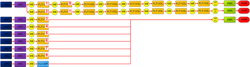
The best practice for flowgraph ordering among commands of a given type is generally to favor depth through a voice’s processing path up to either a submix stage or up to reused SHAPE components. Then favor breadth for voices that share common processing orders.
In Figure 1, typically the optimal approach is to create FLT/VOL commands for the left-most column of FLT/VOLs first, and then to pivot the remaining FLT/VOL commands for the two channels of the top stereo-voice.
Mix buffer instance allocation
Mix buffers are locked while being written to, and no output can be read from them until all inputs have all contributed to the mix. From an implementation perspective, mix buffers use a numIn and numOut fields to manage this. Therefore, you can possibly construct scenarios that require more than the 128 physical mix buffers at the same time.
SHAPE virtualizes mix buffers so that, even for high polyphony, this scenario will not typically cause an issue. However, you can construct flowgraphs that require high numbers of mix buffers accessed concurrently.
In particular, mix buffers that are submixing or mastering among multiple voices are locked until the last voice is mixed into them, and until the last output of the mix buffers is consumed by a subsequent SHAPE block.
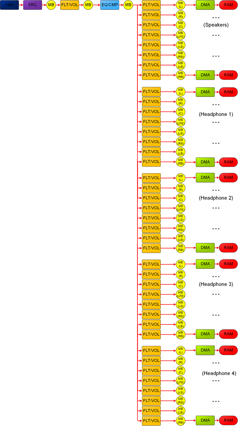
In a fairly typical scenario—a single 7.1 mastering voice that all SHAPE voices are mixed into—8 of the 128 voices are locked throughout the frame. Additional mix buffers could lock for a significant portion of the frame (reducing the capacity for the virtual mix buffers) if there is extensive multichannel submixing with flowgraph dependency chains or additional mastering voices are created—for instance, if you were to create both a main speaker and a 7.1 headset-mix that is per-player for a four-player title, which could consume 40 concurrent mix buffers.
In general, a case that requires more than 128 concurrent physical mix buffers is pathologic; however, mix buffers that are unnecessarily locked for the entire frame reduce your title’s ability to achieve the potential throughput.
The following example may represent unnecessary submixing that could reduce the number of available mix buffers at a given time.
Figure 2. Depending on command ordering, the 5 separate 7.1 mastering mix buffers could be locked throughout nearly the entire frame, which represents 40 of the 128 physical mix buffers. While this path requires only 2 other mix buffers to be in use at a given time—that is, the paired input and output for a FLT/VOL or EQ/CMP—consider processing all of the mix buffers going into speakers first. Then you can free those mix buffers and process headphone 1, headphone 2, and so on.
SHAPE component selection and balancing (FLT/VOL vs. EQ/CMP)
If you use the same SHAPE components repeatedly in sequence, you can reduce the ability to reach the maximum throughput. By comparison, by alternating different components, you ensure that each SHAPE block is doing meaningful parallel processing.
Figure 3. A common example: FLT/VOLs cannot all be processed in parallel. Performance may suffer.
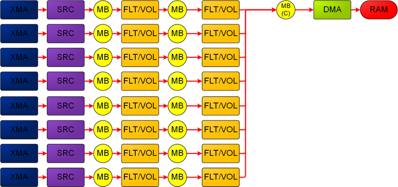
The second set of FLT/VOLs must wait for the first to complete, potentially while other SHAPE blocks remain unused. If either set were used exclusively for filtering, the EQ/CMP might represent a better choice for one set—especially if the flowgraph below with the same configuration has more voices, which can then begin their FLT/VOL while the first set processes its EQ/CMP blocks.
Figure 4. Performance that more closely approaches the ideal SHAPE capabilities. This figure replaces one set of FLT/VOLs, presumed to be used for filtering only, from Figure 3 with EQ/CMP, which allows for parallel processing of the two SHAPE components.
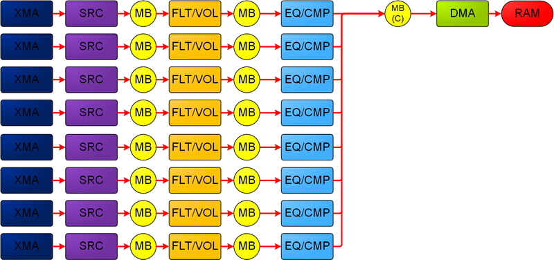
SHAPE component balancing is also relevant when you consider the maximum instancing of the various components. The 2560 FLT/VOL components that can occur within a frame allow the FLT/VOL hardware to run approximately five times more calculations than the 512 EQ/CMP blocks.
If you run an EQ/CMP block in series with a single FLT/VOL, then you will realize less performance than you would by running multiple FLT/VOL components coupled with an EQ/CMP, because the former’s processing will be gated by the latter’s consumption.
Too many or frequent low value DMA roundtrips
DMA is bound by the read/write bandwidth available to the SHAPE’s bus. If you consume all available bandwidth—though this scenario is usually pathological—then DMA blocks will stall and reduce throughput.
As discussed earlier, note that all processing that occurs after a DMA input block will have to wait until the DMA completes; therefore, you can create flowgraphs with much of the flowgraph is blocked, waiting for a DMA to complete before the flowgraph can begin processing.
You should also evaluate DMA roundtrips relative to the value that they present to the audio stream. While the minimal addition of latency (which you can control in terms of the number of frames accessed via DMA at multiples of the 22/3 msec audio-frame size) may not be a concern for most audio playback scenarios, because blocks to the right of a DMA will actually be processing audio data from previous frames.
In particular, sending a DMA back into SHAPE just to perform a final mix may be unnecessary when you also plan to send that final mix as DMA back out to memory for presentation to an audio endpoint.
Figure 5. A potentially low value example where a voice that is sent via DMA to memory for CPU/GPU processing is brought back into SHAPE, only to be 7.1 panned into the mastering mix. The voice is then sent via DMA back out to memory. This example assumes that no filtering is being applied to voice in the FLT/VOL blocks and that the 7.1 mastering mix buffers have additional voices routed to them.
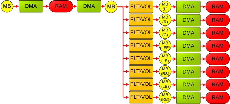
Figure 6. A potentially more optimal routing of Figure 5’s intent. The voice is sent via DMA to memory for CPU/GPU processing. The voice can then be 7.1 panned and combined with the rest of the 7.1 mix on the CPU itself without the overhead of additional DMAs, additional audio frame latency, or use of seven FLT/VOL components.
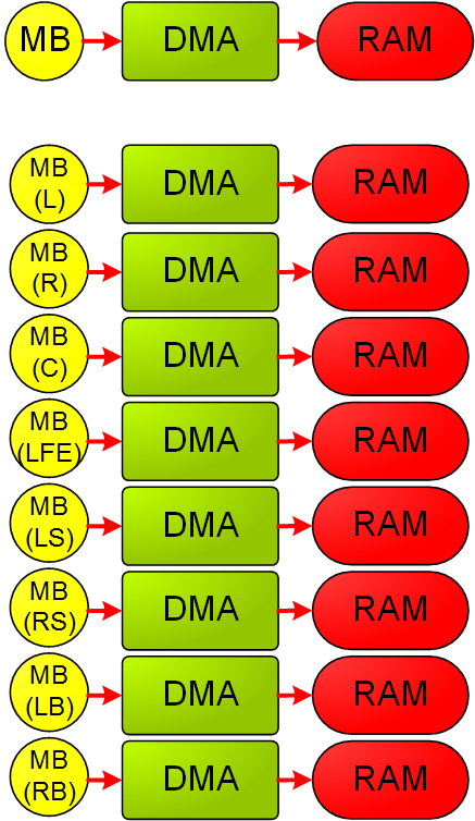
When you eliminate DMAs from the process, you must make sure that you don’t eliminate too many; you can justify using roundtrip DMAs if you intend a significant amount of additional SHAPE processing for a given voice, or if you want to take advantage of the hardware metering and clip detection that the mix buffers afford.
SHAPE flowgraph planning and review
As a useful exercise, before implementation you can create a visual representation of a flowgraph of the voice use that you expect within a frame, with the voices categorized and quantified—for example, how many sound effects and how many concurrent streams of music.
Visually capturing this information can help you better understand how to avoid some of the performance pitfalls discussed in earlier sections. Key metrics that you can derive from such a flowgraph include:
- Maximum number of each SHAPE component, both concurrent and within the overall frame
- Validate that this flowgraph falls sufficiently below the theoretical peaks.
- Note the under and overutilization of components, and rebalance the components as necessary.
-
Note and consider restructuring mix buffer use if too many are required to remain locked through most of the flowgraph.
- Planning for 3D-positioning implementation via SHAPE.
- Will all voices be 7.1 panned? Or will the voices be panned between 2 or n closest speakers?
-
Should all 7.1 panning be done in SHAPE? Or are voices that have already been sent via DMA to the CPU best panned on the CPU itself?
- Number of DMA transitions to and from memory, and whether these transitions are asymmetrical (for example, some voices are written in/out to SHAPE more times than others, which means they will likely have additional latency).
Flowgraph construction can also inform discussions between audio designers and engine or audio middleware developers, ensuring dynamically or statically created graphs are correctly created and routed as desired.
Persistent versus non-persistent flowgraphs
You can submit flowgraphs to be processed as persistent or non-persistent.
Persistent flowgraphs process and then remain resident to repeat their processing in the next frame once read and write pointers have advanced and once other context information is updated. You can use persistent flowgraphs for either of the following scenarios:
- Highly complex flowgraphs: Those flowgraphs that require a significant amount of CPU processing to reassemble each frame.
- Highly static flowgraphs: Those flowgraphs with the same number and configuration of voices for an extended period of time.
Use non-persistent flowgraphs for any of the following situations:
- Voice topologies are changing often.
- The processing cadence of your title’s audio software engine is detached from the SHAPE hardwareùthat is, not a multiple of 2.667 msec.
- You want to run audio processing in faster-than-real-time scenarios—that is, when you submit graphs to be consumed as quickly as they are available.
Debugging SHAPE issues
We recommend that when you are developing flowgraphs, you register for messages to help debug issues that might occur. Specifically, use the NumMessages parameter of IAcpHal::Connect Method.
The messaging system provides rich feedback on a variety of issues, including invalid flowgraphs—for example, ACP_FLOWGRAPH_TERMINATED_REASON_INVALID_GRAPH—blocked commands, and frameouts that are caused when you attempt to perform more processing than the hardware frame size of 2.667 msec allows.
Although this method is helpful for debugging, before your title ships, ideally you should eliminate all error-indicating messages from run-time scenarios, and verify consistently successful flowgraph processing by witnessing ACP_MESSAGE_TYPE_FLOWGRAPH_COMPLETED messages—see ACP_MESSAGE_TYPE Enumeration—for each submitted flowgraph.
Missed messages
Particularly if you use ACP messages to drive engine state, and if you handle a large number of messages, then during development you should examine ACP_MESSAGE::droppedMessageCount. A non-zero value indicates that the message queue was full and messages had to be dropped. If this value occurs, consider servicing the queue faster and also making the queue larger.
Frame outs
For a variety of reasons during development (such as over-budget or suboptimal flowgraphs), a flowgraph might not complete before the end of an audio frame (2.667 msec) is encountered. This incomplete flowgraph will result in an ACP_FLOWGRAPH_TERMINATED_TIME_EXCEEDED message for persistent flowgraphs, and these persistent flowgraphs will be incomplete.
By contrast, a non-persistent flowgraph is not constrained in this manner, and the flowgraph will run until completed—even across frames.
Blocked commands
SRC and DMA commands can report as blocked (ACP_MESSAGE_TYPE_SRC_BLOCKED, ACP_MESSAGE_TYPE_DMA_BLOCKED—see ACP_MESSAGE_TYPE Enumeration) in several scenarios:
| Command type | Reports blocked when… |
|---|---|
| XMA SRC | The associated XMA context has a parser error or no source data(error: SHAPE_XMA_ERROR_STATUS_READ_BUFFER_INVALID_VALIDBUFFER_CURRBUF_IS_0 | SHAPE_XMA_ERROR_STATUS_FRAME_CROSSES_BOUNDARY_INTO_INVALID_READ_BUFFER_VALIDBUFFER_CURRBUF_IS_0 | SHAPE_XMA_ERROR_STATUS_FRAME_CROSSES_BOTH_READ_BUFFER_BOUNDARIES)XMA SRC will not block based on a lack of decoded data. |
| PCM SRC | Associated PCM context is SHAPE_PCM_MODE_CIRCULAR and there is no source data. |
| Read (DMA from mixbuffer) | DMA buffer is full. |
| Write (DMA to mixbuffer) | DMA buffer is empty. |
Once commands are determined to be blocked—which occurs both before being added to a SHAPE queue for processing and at run time—commands are evicted from the graph, which can lead to dropped audio. During development, you should use blocked commands as the first place to look for flowgraph-handling improvements, and before shipping, your title should prevent commands from being blocked.
You can prevent blocked DMA commands by ensuring that your audio buffer is sufficiently large and that data is streamed at regular intervals, related to the buffer size. For example, if you are streaming 4 hardware frames at a time, ensure some multiple of those frames—at least double-buffered at 8—are in the buffer so the hardware can write ahead of the title’s read pointer.
Alternatively, you could enforce emptying the buffer before submitting the next flowgraph: consume, update DMA read pointer, and then submit the flowgraph.
Note that SRC commands have three modes, as detailed in ShapeSrcContext.h:
SHAPE_SRC_COMMAND_TYPE_START
Used for nearly all SRC commands in a flowgraph (process normally and expect more audio data to follow the current flowgraph).
SHAPE_SRC_COMMAND_TYPE_STOP_IMMEDIATE
Immediate stop processing the source XMA or PCM data. The SRC will output a zeroed buffer for this frame.
SHAPE_SRC_COMMAND_TYPE_STOP_END
Used to indicate the last packet of a voice.
If the last packet of a voice is not submitted with STOP_END (or STOP_IMMEDIATE), then the SRC command will not complete—causing the active flowgraph to stall. A persistent flowgraph will terminate at the end of the audio frame, and a non-persistent flowgraph will never complete.
Synchronization issues
A number of synchronization issues can arise if you do not respect the SHAPE hardware’s consumption practices for contexts and commands. While your titles retain full access to ACP-allocated memory, take care not to modify a context structure while it is in use. You can submit commands—IAcpHal::SubmitCommand—to occur at a specific frame, at the beginning of the next frame, or as soon as possible.
For the last scenario (commands occurring as soon as possible), be aware that as soon as possible is still asynchronous from any title CPU processing. Some commands may not complete immediately—for instance, if a context is in the middle of a non-interruptible operation. Wait for an ACP_MESSAGE_TYPE_COMMAND_COMPLETED to verify that a command has been truly processed.