Bokeh Blurring Effect
The bokeh effect is the blurring of anything behind or in front of the Depth of Field (DOF) area. The word ‘bokeh’ is Japanese for ‘blur’. Bokeh and Depth of Field are terms that originate in photography. When a picture is taken, certain areas of the photo are in focus, and sharply displayed. Other areas are out of focus and blurry. Depth of Field refers to the area of apparent sharpness. 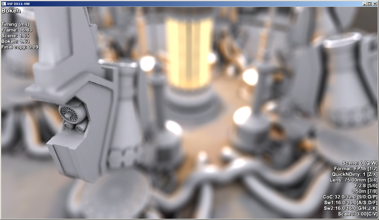
The following sections describe the bokeh effect and how to render it on the Xbox One dev kit:
For a working bokeh sample, download the Bokeh sample from the XDK Samples on the Xbox Game Developer (XGD) site. For additional instructions, see Running the XDK Samples.
How the bokeh effect works
The bokeh effect is an important artistic tool that has found its way into computer generated graphic images. In photography, depth of field (DOF) is determined by lens focal length, aperture and the distance to the subject and is approximately given by a thin lens equation. In computer graphics it is possible to use arbitrary parameters and formulae for DOF, although it is convenient to define them as in photography.
Bokeh occurs in real-world photography because the light picked up from of out-of-focus objects is diffused by the lens and extended into a circle on film. The affected area is known as the Circle of Confusion (CoC). For an example of CoC, consider a night-time photograph of a city. Objects in focus are sharply defined, but lights in the background appear blurry like large globes instead of pinpoints of light.
Focal Distance: The distance from the camera at which objects appear in-focus.
Focal Depth: The volume of space in front and behind the focal distance in which objects appear in-focus. Larger focal depths mean a larger area of the screen will be in-focus.
Rendering bokeh
Graphically, we can utilize the Circle of Confusion concept to create a convincing bokeh effect. Circles of Confusion are represented by colored point sprites, and all of the sprites are blended together to create the blurring effect. This is done as a post-processing effect, the scene has already been rendered to a pixel buffer. To render the bokeh effect, check the z-depth and color of every pixel in the pixel buffer.
The pixel buffer must be broken into three segments: Far pixels, In-Focus pixels, and Near pixels. Near and Far pixels both generate circles of confusion based on distance. In-Focus pixels should not be obscured by CoC’s generated by Far pixels. CoCs that are generated by near pixels can obscure In-Focus pixels. For Far pixels, the CoC should get larger as distance from the camera increases. The opposite is true of Near pixels: the closer they are, the larger the CoC.
Algorithm for rendering bokeh
- Render the scene to a Shader Resource View.
- Convert SRV data to an RGBZ texture. (Z for z-depth).
- Downsample the RGBZ texture once.
- For a downsampled RGBZ texture of size WxH, set up a render target with 6 viewports — a pair of each: WxH, (W/2)x(H/2), and (W/4)x(H/4).
- Render (W*H)/4 point primitives.
- For each point primitive read 4 RGBZ values of the downsampled source texture.
- If the 4 pixels don’t differ much, output one sprite, otherwise output 4 sprites.
- Depending on the size of the sprite route it into a corresponding viewport, sprites nearer than in-focus area going into the “near” set of viewports; sprites farther away go into the “far” set of viewports.
- After finishing rendering the 6 viewports, recombine them with the in-focus image, making sure in-focus pixels override the far blurred area and the near pixels blend over the in-focus and far pixels.
To improve blending of the near blurred pixels, image energy conservation is important. Each source pixel has unit energy, so after splatting it with a point sprite, that energy is distributed over the area of the sprite. Due to different iris textures and rasterization rules, it’s impossible to calculate the weight in closed form for all sizes and sprite origins. The XDK Bokeh sample renders the iris sprite at different sizes and calculates the resulting weight, then computes the normalization factor.
Rendering the scene to a Shader Resource View
You will need a pointer to the Shader Resource View. During initialization, you will need to create a buffer description for your SRV, and set the SRV pointer.
C++
D3D11_SHADER_RESOURCE_VIEW_DESC srvDesc;
srvDesc.Format = DXGI_FORMAT_R16_FLOAT;
srvDesc.ViewDimension = D3D11_SRV_DIMENSION_TEXTURE1D;
srvDesc.Texture1D.MostDetailedMip = 0;
srvDesc.Texture1D.MipLevels = 1;
XSF_RETURN_IF_FAILED( pDev->CreateShaderResourceView( m_spEnergiesTex, &srvDesc, m_spEnergiesTexSRV.GetAddressOf() ) );
Converting SRV to RGBZ texture
To convert SRV data to an RGBZ texture, you will need two Shader Resource View pointers, one pointing to the color SRV, and another pointing to the Depth SRV. Additionally, you will need a pointer to the RGBZ texture that you wish to render.
Set up the data conversion from SRV to RGBZ texture:
C++
// copy out the source
// this is 0.2 ms faster than CopyResource
pCtx->OMSetRenderTargets( 1, m_spSourceColorTextureRGBZCopyRTV.GetAddressOf(), nullptr );
pCtx->RSSetViewports( 1, &vpResult );
pCtx->PSSetShaderResources( 0, 1, &pSrcColorSRV );
pCtx->PSSetShaderResources( 2, 1, &pSrcDepthSRV );
pCtx->VSSetShader( m_spQuadVS, nullptr, 0 );
pCtx->GSSetShader( nullptr, nullptr, 0 );
pCtx->PSSetShader( m_spCreateRGBZPS, nullptr, 0 );
pCtx->IASetPrimitiveTopology( D3D11_PRIMITIVE_TOPOLOGY_TRIANGLESTRIP );
pCtx->Draw( 4, 0 );
The actual conversion process from SRV to RGBZ happens in a vertex and pixel shader:
C++
// output a quad
PSSceneIn  VSQuad( uint index : SV_VertexID )
{
    uint corner = index % 4;

    static const float4    posuv[ 4 ] =
    {
        float4( -1, -1, 0, 1 ),
        float4( -1,  1, 0, 0 ),
        float4(  1, -1, 1, 1 ),
        float4(  1,  1, 1, 0 ),
    };

    PSSceneIn output;
    output.pos = float4( posuv[ corner ].xy, 0.5f, 1.0 );
    output.tex = posuv[ corner ].zw;

    return output;
}

// this creates a full screen version of the RGBZ texture from a source colour and depth texture
float4  PSCreateRGBZ( in float2 dummy : TEXCOORD0, in float4 p : SV_Position ) : SV_Target
{
    uint2   pos = uint2( p.xy );
    float3  color = t0.Load( uint3( pos, 0 ) ).xyz;

    const BokehInfo    i = GetBokehInfo( pos );

    return float4( color, i.fDepth );
}
Generating six viewports
You will need to generate six viewports to contain the downsampled RGBZ textures. Three viewports for Far objects, and three viewports for Near objects. These viewports are used for downsampled versions of the main RGBZ source texture. If the RGBZ source has dimensions (2W)x(2H), then Near and Far will each use a viewport of size WxH, (W/2)x(H/2), and(W/4)x(H/4).
C++
// output into several viewports
const FLOAT vpSx  = (FLOAT)texDesc.Width  / FIRST_DOWNSAMPLE;
const FLOAT vpSy  = (FLOAT)texDesc.Height / FIRST_DOWNSAMPLE;
const FLOAT vpSx2 = (FLOAT)texDesc.Width  / (2 * FIRST_DOWNSAMPLE);
const FLOAT vpSy2 = (FLOAT)texDesc.Height / (2 * FIRST_DOWNSAMPLE);
const FLOAT vpSx4 = (FLOAT)texDesc.Width  / (4 * FIRST_DOWNSAMPLE);
const FLOAT vpSy4 = (FLOAT)texDesc.Height / (4 * FIRST_DOWNSAMPLE);
const D3D11_VIEWPORT vpOutput[ 6 ] =
{
    // big ones one below another
    { 0, 0,    vpSx, vpSy,  0, 1 },
    { 0, vpSy, vpSx, vpSy,  0, 1 },

    // smaller ones along the bottom
    { 0,     vpSy*2, vpSx2, vpSy2,  0, 1 },
    { vpSx2, vpSy*2, vpSx2, vpSy2,  0, 1 },

    // smaller ones still along the bottom again
    { 0,     vpSy*2 + vpSy2, vpSx4, vpSy4,  0, 1 },
    { vpSx4, vpSy*2 + vpSy2, vpSx4, vpSy4,  0, 1 },
};
Getting a downsampled RGBZ texture
Now that we have the RGBZ texture, we need a downsampled version of the texture. The downsampled texture is half the width and height of the full size RGBZ texture, and has ¼ as many pixels. This means that every 2x2 grid of pixels in the full size texture will be condensed to a single pixel in the downsampled texture. The new pixel takes the average color of the original pixels, and the minimum z-depth of the four pixels.
Prepare to downsample an RGBZ texture to half size:
C++
// render downsample
pCtx->OMSetRenderTargets( 1, m_spSourceColorTextureRGBZHalfCopyRTV.GetAddressOf(), nullptr );
pCtx->RSSetViewports( 1, &vpResultHalf );
pCtx->PSSetShaderResources( 0, 1, m_spSourceColorTextureRGBZCopySRV.GetAddressOf() );
pCtx->PSSetShader( m_spDownsampleRGBZPS, nullptr, 0 );
pCtx->IASetPrimitiveTopology( D3D11_PRIMITIVE_TOPOLOGY_TRIANGLESTRIP );
pCtx->Draw( 4, 0 );
pCtx->PSSetShaderResources( 0, 1, (ID3D11ShaderResourceView**)&null );
A pixel shader does the actual downsampling work:
C++
// downsample the RGBZ texture
float4  PSDownsampleRGBZ( in float2 dummy : TEXCOORD0, in float4 p : SV_Position ) : SV_Target
{
    float3  color = t0.Sample( s0, dummy ).xyz;
    float4  depths = t0.GatherAlpha( s0, dummy );
    float   depth = min( depths.x, min( depths.y, min( depths.z, depths.w ) ) );

    return float4( color, depth );
}
Rendering point primitives
We will render to the six viewports created earlier. There is a point primitive for every pixel of the RGBZ source texture. Examine the point primitives, determine the size of the CoC, and blend the pixels together. Render to the correct viewports, or else the final image will not look right.
Rendering to multiple viewports:
C++
// prepare the multi-viewport dof render target
pCtx->OMSetRenderTargets( 1, m_spDOFColorRTV.GetAddressOf(), nullptr );
pCtx->RSSetViewports( _countof( m_vpSplitOutput ), m_vpSplitOutput );

// split into slices, do the CoC DOF
pCtx->VSSetShader( m_spQuadPointVS, nullptr, 0 );
pCtx->GSSetShader( m_spQuadPointGS, nullptr, 0 );
pCtx->PSSetShader( m_spQuadPointPS, nullptr, 0 );

pCtx->VSSetShaderResources( 0, 1, m_spSourceColorTextureRGBZHalfCopySRV.GetAddressOf() );
pCtx->GSSetShaderResources( 0, 1, m_spSourceColorTextureRGBZHalfCopySRV.GetAddressOf() );
pCtx->PSSetShaderResources( 1, 1, m_spIrisTex.GetAddressOf() );

FLOAT black[ 4 ] = { 0 };
pCtx->OMSetBlendState( m_spPointsBS, black, D3D11_DEFAULT_SAMPLE_MASK );

pCtx->IASetPrimitiveTopology( D3D11_PRIMITIVE_TOPOLOGY_POINTLIST );
pCtx->Draw( texDesc.Width * texDesc.Height / (FIRST_DOWNSAMPLE * FIRST_DOWNSAMPLE * 2 * 2), 0 );    // each GS can output up to 4 triangles
HLSL code:
C++
// the runtime requires a vertex shader at all times, and we don't need it to render point sprites, so we have to use an empty VS
void VSQuadPoint()
{
}

// we haven't got anything coming from the VS, but the compiler needs to know the input types
// so we create this empty struct to keep the compiler happy
struct Empty {};

// This converts a point into a sprite(GENERATE POINTSPRITE TO REPRESENT COC FOR THIS PIXEL)
// It routes the viewport index to GS output so that the geometry ends up in the correct viewport
// There is a point primitive for each pixel of the source RGBZ texture, this shader reads the
// point primitive and the texel value, calculates the CoC, then normalisation factor, then
// decides which viewport to output the sprite to and whether to output one or four sprites, then
// finally expands the point into a sprite
[maxvertexcount( 12 )]  // we output from 1 to 4 triangle sprites so we need space for up to 12 output vertices
void    GSQuadPoint(    point Empty p[ 1 ],
                        uint inst0 : SV_PrimitiveID,        // VertexID == PrimitiveID for point lists
                        inout TriangleStream< PSSceneInPoint > spriteStream )
{
    const uint topLeftX = 2 * ((inst0) % uint(g_screenSize.x / (FIRST_DOWNSAMPLE * 2)));
    const uint topLeftY = 2 * ((inst0) / uint(g_screenSize.x / (FIRST_DOWNSAMPLE * 2)));

    GSSceneInPoint  pt[ 4 ];

    uint i;
    for( i=0; i < 4; ++i )
    {
        const uint    xx = topLeftX + (i % 2);
        const uint    yy = topLeftY + (i / 2);

        pt[ i ] = GenerateSpritePointFromXY( xx, yy );
    }

    // if we can output only 1 sprite, this saves us tons of time
    bool bOutputOne = true;

    if( (pt[ 0 ].viewportIndex != pt[ 1 ].viewportIndex) ||
        (pt[ 0 ].viewportIndex != pt[ 2 ].viewportIndex) ||
        (pt[ 0 ].viewportIndex != pt[ 3 ].viewportIndex) )
    {
        bOutputOne = false;
    }

    const float radiusThreshold = 1;
    const float colorThreshold = 0.2f;

    if( abs( pt[ 0 ].radius - pt[ 1 ].radius ) > radiusThreshold    ||
        abs( pt[ 0 ].radius - pt[ 2 ].radius ) > radiusThreshold    ||
        abs( pt[ 0 ].radius - pt[ 3 ].radius ) > radiusThreshold )
    {
        bOutputOne = false;
    }

    if( distance( pt[ 0 ].clr, pt[ 1 ].clr ) > colorThreshold    ||
        distance( pt[ 0 ].clr, pt[ 2 ].clr ) > colorThreshold    ||
        distance( pt[ 0 ].clr, pt[ 3 ].clr ) > colorThreshold )
    {
        bOutputOne = false;
    }

    // causes artefacts near the boundary so don't attempt to optimise near the boundary
    if( pt[ 0 ].radius < 4.f )
        bOutputOne = false;


    if( bOutputOne )
    {
        // TODO: properly merge, this is a quick hack
        GSSceneInPoint mergedSprite;

        mergedSprite.clr = 0.25f * (pt[ 0 ].clr + pt[ 1 ].clr + pt[ 2 ].clr + pt[ 3 ].clr );
        mergedSprite.weight = 0.25f * (pt[ 0 ].weight + pt[ 1 ].weight + pt[ 2 ].weight + pt[ 3 ].weight ) * 4; // TODO: max weight?
        mergedSprite.radius = 0.25f * (pt[ 0 ].radius + pt[ 1 ].radius + pt[ 2 ].radius + pt[ 3 ].radius );
        mergedSprite.pos = 0.25f * (pt[ 0 ].pos + pt[ 1 ].pos + pt[ 2 ].pos + pt[ 3 ].pos );
        mergedSprite.viewportIndex = pt[ 0 ].viewportIndex;

        EmitSpriteIfBigEnough( mergedSprite, spriteStream, mergedSprite.clr );
    } else
    {
        // this colour will only be used if a sprite goes into a smaller render target
        float3 averageColor = 0.25f * (pt[ 0 ].clr + pt[ 1 ].clr + pt[ 2 ].clr + pt[ 3 ].clr );
        for( i=0; i < 4; ++i )
        {
            EmitSpriteIfBigEnough( pt[ i ], spriteStream, averageColor );
        }
    }
}

// the last step -- output alpha premultiplied colour using this trivial pixel shader
float4 PSQuadPoint( PSSceneInPoint input ) : SV_Target
{
    float    iris = t1.Sample( s0, input.uv ).x;

    float   w = input.weight * iris;
    if( w <= 0 )
        clip( -1 );

    float4 c = float4( input.clr.xyz, 1 ) * w;

    return c;
}
Calculate the size of a Circle of Confusion (CoC)
You can use any method you like to calculate the size of a CoC, so long as the method obeys the following basic requirements:
- Any Pixels with a Z-Depth greater than (Focal Distance + Focal Depth) are in the ‘Far’ category. Point sprites should be generated for these pixels, higher Z-Depths generate larger point sprites.
- Pixels with a Z-Depth between (Focal Distance + Focal Depth) and (Focal Distance – Focal Depth) are ‘In Focus’ and do not expand to sprites. (Or, sprites with a pixel diameter of 1.)
- Pixels with a Z-Depth less than (Focal Distance – Focal Depth) are in the ‘Near’ category. Point sprites generated for these pixels should get larger as Z-Depth gets smaller.
The calculation should return the radius of the CoC in pixels.
C++
// calculates the size of CoC given the linear depth of a pixel.
// it uses a thin lens formula from photography so you can control DOF blur as you would
// on a camera -- by changing the aperture and focus length.
float   CalculateCoC( in float fDepth, out float fDepthDifference )
{
    fDepthDifference = fDepth - g_fFocalPlane;

    const float var = abs( fDepthDifference ) / fDepth;
    const float cnst = g_fFocusLength * g_fFocusLength / (g_fFNumber * (g_fFocalPlane - g_fFocusLength));
    const float cocMetersRadius = 0.5f * var * cnst;                  // coc radius in meters
    const float cocRelativeToFilm = cocMetersRadius / 0.035f;         // size relative to 35mm sensor
    const float cocRadiusInPixels = g_depthBufferSize.x * cocRelativeToFilm;

    return min( (fDepthDifference < 0) ? g_fMaxCoCRadiusNear : g_fMaxCoCRadiusFar, cocRadiusInPixels );
}
Recombine viewports with original image
Now that all of the point sprites have been generated and rendered into the corresponding viewports, it is time to recombine the viewports with the source SRV for the final image. Render the Far viewports first, because CoCs generated by Far objects should not obscure pixels in the Focal or Near ranges. Render the Focal objects second. Near objects are rendered last, because the CoCs generated by Near pixels should obscure anything in the Focal or Far ranges.
Combining multiple viewports together:
C++
    // combine the resulting viewports
    pCtx->RSSetViewports( 1, &vpResult );
    pCtx->OMSetRenderTargets( 1, &pDstRTV, nullptr );

    // the 2 viewports are in one texture
#if defined(_XBOX_ONE) && defined(_TITLE)
    if( fastSemanticsEnabled )
    {
        pCtx->DecompressResource( m_spDOFColorTexture.Get(), 0, nullptr, m_spDOFColorTexture.Get(), 0, nullptr, DXGI_FORMAT_UNKNOWN, D3D11X_DECOMPRESS_PROPAGATE_COLOR_CLEAR );
    }
#endif
    pCtx->PSSetShaderResources( 0, 1, m_spDOFColorSRV.GetAddressOf() );
    pCtx->PSSetShaderResources( 1, 1, m_spIrisTex.GetAddressOf() );
    pCtx->PSSetShaderResources( 2, 1, &pSrcDepthSRV );
    pCtx->PSSetShaderResources( 3, 1, m_spSourceColorTextureRGBZCopySRV.GetAddressOf() );  // pSrcColorSRV

    pCtx->VSSetShader( m_spQuadVS, nullptr, 0 );
    pCtx->GSSetShader( nullptr, nullptr, 0 );
    pCtx->OMSetBlendState( nullptr, black, D3D11_DEFAULT_SAMPLE_MASK );

    pCtx->IASetPrimitiveTopology( D3D11_PRIMITIVE_TOPOLOGY_TRIANGLESTRIP );

    pCtx->PSSetShader( m_spRecombinePS, nullptr, 0 );

    pCtx->Draw( 4, 0 );
HLSL code:
C++
// after all the layers are generated, this step combines them with the in-focus image for the final image
// in-focus image occludes far layer and the near layer occludes both in-focus and far layers
float4 PSRecombine( PSSceneIn input ) : SV_Target
{
    // full resolution in-focus colour and linear depth
    float4 rgbz = t3.Load( uint3( input.tex * g_screenSize, 0 ) );

    BokehInfo    i;
    i.fCoCRadius = CalculateCoC( rgbz.w, i.fDepthDifference );

    float4 c = float4( rgbz.xyz, 1 );

    // in focus area totally obscures far range and is always weight = 1
    // this doesn't have to be exclusive, it's possible to blend one into another over a range of CoC values
    if( i.fCoCRadius > 1.0f &&
        i.fDepthDifference > 0 )
    {
        float2  texUvFar  = (( input.tex * g_viewports[ 1 ].zw ) + g_viewports[ 1 ].xy) / g_dofTexSize;
        float2  texUvFar2 = (( input.tex * g_viewports[ 3 ].zw ) + g_viewports[ 3 ].xy) / g_dofTexSize;
        float2  texUvFar4 = (( input.tex * g_viewports[ 5 ].zw ) + g_viewports[ 5 ].xy) / g_dofTexSize;

        float4  clrFar   = t0.Sample( s0, texUvFar );
        float4  clrFar2  = t0.Sample( s0, texUvFar2 );
        float4  clrFar4  = t0.Sample( s0, texUvFar4 );

        float4 far = clrFar + clrFar2 + clrFar4;

        c = lerp( c, far, min( 1, i.fCoCRadius - 1 ) );   // a small blend over to cover the transition

        // normalize so the image doesn't get brighter or dimmer
        if( c.w > 0.00001f )
          c.xyz /= c.w;

        c.w = 1;
    }

    // blend in the near layer
    float2  texUvNear  = (( input.tex * g_viewports[ 0 ].zw ) + g_viewports[ 0 ].xy) / g_dofTexSize;
    float2  texUvNear2 = (( input.tex * g_viewports[ 2 ].zw ) + g_viewports[ 2 ].xy) / g_dofTexSize;
    float2  texUvNear4 = (( input.tex * g_viewports[ 4 ].zw ) + g_viewports[ 4 ].xy) / g_dofTexSize;

    float4  clrNear  = t0.Sample( s0, texUvNear );
    float4  clrNear2 = t0.Sample( s0, texUvNear2 );
    float4  clrNear4 = t0.Sample( s0, texUvNear4 );

    float4 near = clrNear + clrNear2 + clrNear4;

    if( near.w > 0 )
    {
        float occlusion = 0;

        if( i.fCoCRadius >= 1.0f &&
            i.fDepthDifference < 0 )
        {
            float nearToInFocusTransition = min( 1, (i.fCoCRadius - 1) );
            occlusion = max( occlusion, nearToInFocusTransition );   // a small blend over to cover the transition
        }

        // Occlusion can be greater than one due to unnormalised energy at this point
        // so we only interpolate when occlusion is less than one, otherwise we assume
        // near range fully obscures far range
        if( occlusion < 1 )
            c = c * (1 - min( 1, near.w ) ) + near;
        else
            c = near;

        // normalize so the image doesn't get brighter or dimmer
        if( c.w > 0.00001f )
            c.xyz /= c.w;
    }

    return float4( c.xyz, 1 );
}