Point Sprites
Point sprites are 2D textures that are drawn onscreen in a 3D application. On the Xbox One dev kit, render point sprites as follows.
- Overview of Point Sprites
- Data Arrangement
- Triangles vs. Quads
- Choosing a rendering approach
- Example: Rendering a Point Sprite using the Vertex Shader approach
Overview of Point Sprites
Point sprites are 2D textures that are drawn onscreen in a 3D application. Point sprites can be used for a variety of purposes, from HUD elements to particle effects. An entire 2D game could be made using only point sprites.
Point sprites can be drawn at several stages of the rendering pipeline: the Geometry Shader, the Vertex Shader, the Tessellator, an Instanced Vertex Shader, or a combination of Geometry Shader and Vertex Shader. In all five instances, the sprites will need to be drawn using either a triangle or a quad, for a total of ten possible combinations. Some approaches for rendering point sprites will perform better than others, depending on the circumstances and implementation.
Regardless of which rendering approach you choose, much of the process will be the same. The texture must be rendered on a polygon, usually either a triangle or a quad. The texture coordinates are mapped to the polygon in the same manner that they would be mapped to a 3D object. The sprites are stored as a single point to reduce memory footprint and calculation times. If a large number of sprites are being displayed, an array should be used to store them.
Data Arrangement
You must define your own point sprite class, because there is no pre-existing point sprite class. Or, you can arrange your data in an array instead of defining a class. Every point sprite requires at least the following data: X/Y position (within screen bounds), size, and a pointer to the texture to be drawn. Alternatively, you can save space by sharing a common texture, and populating an array with sprite position, size, and color data.
An example of point sprite array initialization:
C++
static FLOAT vbData[ 7 * NUM_PARTICLES ];   // create array of particles.
for( UINT i=0; i < NUM_PARTICLES; ++i )
{
    FLOAT* p = &vbData[ i * 7 ];            // each particle uses 7 floats. Xpos, Ypos, size, and RGBA values

    p[ 0 ] = GetBackbuffer().GetViewport().Width * (float)rand() / (float)RAND_MAX;
    p[ 1 ] = GetBackbuffer().GetViewport().Height * (float)rand() / (float)RAND_MAX;
    p[ 2 ] = fMaxParticleSize * (float)rand() / (float)RAND_MAX;

    p[ 3 ] = (float)rand() / (float)RAND_MAX;
    p[ 4 ] = (float)rand() / (float)RAND_MAX;
    p[ 5 ] = (float)rand() / (float)RAND_MAX;
    p[ 6 ] = (float)rand() / (float)RAND_MAX;
}
Triangles vs. Quads
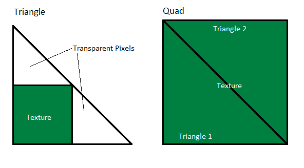
Point sprites cannot be rendered without a polygon to map the texture coordinates onto. The most commonly used polygons are triangles and quads (two triangles that form a square).
Choosing whether to use triangles or quads depends on the desired implementation; typically triangles are used to render small point sprites, while larger point sprites use quads. Triangles require half as many vertices and draw calls, but this performance improvement is offset by the transparent pixels. (Transparent pixels are pixels that are within the polygon, but are not covered by the texture, and therefore are not modified in the draw call. However, the shader must still interact with these pixels during the draw call, affecting performance.) Quads have no transparent pixels, but may be slower in large quantities due to the increased vertex count. Experiment with triangles and quads, and choose the option that performs best for your implementation.
Choosing a rendering approach
Point sprites can be rendered in every geometry related stage of the GPU: Vertex Shader, Geometry Shader, and the Tessellator (Hull and Domain Shader). The ideal choice (or choices, not mutually exclusive) depends on your particular implementation, so be sure to experiment and choose whichever rendering approach performs best. Below are descriptions and implementation samples for these five rendering approaches.
- Geometry Shader & Vertex Shader
- Geometry Shader only
- Vertex Shader only
- Instanced Vertex Shader
- Tessellator
Geometry Shader & Vertex Shader
This is the rendering approach widely advertised in the documents and presentations showing how to port D3D9 point sprites to D3D10. The pipeline is set up so that the vertex shader reads the vertex normally, and then the geometry shader outputs either a quad or a triangle per input vertex.
Advantages
- Well-known and simple.
Disadvantages
- Requires the most setup time.
- Not always the fastest option.
Geometry Shader only
This rendering approach uses an empty vertex shader. To load the vertex data, the geometry shader performs buffer loads on a raw byte view of a vertex buffer, using the SV_PrimitiveID index. For point lists, SV_PrimitiveID in the geometry shader is the same as SV_VertexID in the vertex shader. After the vertex is loaded, the point sprite expansion is performed as in the Geometry Shader & Vertex Shader rendering approach.
Advantages
- No input layout required, because the vertex shader is a no-op.
- Performs faster than the Geometry Shader & Vertex Shader rendering approach, due to no internal traffic between the VS and the GS.
Disadvantages
- A manual vertex load requires different shaders for loading a different vertex layouts. For highly optimized code, this is not a problem.
- This rendering approach is a bit more difficult to understand.
Vertex Shader only
Using a geometry shader just to expand a point into a quad or a triangle is not really required in DX11, and a vertex shader can be used to do that instead. In DirectX 11, the vertex shader stage can read raw byte UAVs, so having SV_VertexID and the raw byte view of the vertex buffer, it’s possible to read the vertex manually.
So to expand the vertex into a triangle or a quad, we just need to render either 3 times more or 6 times more vertices in the draw call, perform division by 3 or 6 in the shader to get the index of the vertex, load the vertex using this index, and expand it based on the remainder of the division to get the sprite’s corner.
Advantages
- So far this is the fastest approach to rendering point sprites. This approach is more than 3 times faster than any geometry shader rendering approach for small sprites (geometry-limited cases) and is still about 50% faster on bigger sprites.
- No input layout required for the VS, it only consumes a system generated value SV_VertexID.
Disadvantages
- Vertex load is manual so a different shader may be needed for loading a different vertex layout.
Instanced Vertex Shader
We can use instancing to make the GPU to load point sprite vertices for us and SV_VertexID to determine the corner of the sprite for expansion. This approach is slightly slower than the previous approach, but still consistently faster than any other approaches
Advantages
- This is the 2nd-fastest approach, with performance similar to the “Vertex Shader only” approach.
- No division is required so the shader has fewer ALUs.
- Vertex load is performed using input layouts so it’s possible to load different vertex layouts without modifying the shader.
- Usually the winning approach for very large sizes of point sprites.
Disadvantages
- None.
Tessellator
It’s possible to use the tessellator stage to generate triangles and quads from a single input vertex. This approach’s performance is similar to the geometry shader-based approaches, but it is more flexible, because more sprite shapes are possible. For example, by tessellating in quad domain, it is possible to output circles instead of quads – this might be more efficient if the pixel shader is very slow and the sprites are circles.
Advantages
- Can output almost arbitrary geometry shapes.
Disadvantages
- A manual vertex load requires different shaders for loading a different vertex layouts. For highly optimized code this is not a problem.
- This approach is a bit more difficult to understand.
Example: Rendering a Point Sprite using the Vertex Shader approach
Each rendering approach performs best under a certain of circumstances. You must choose the approach or approaches that work best for your project. In most cases however, the Vertex Shader is the fastest approach. The following code samples demonstrate how to render triangles and quads using the vertex shader. For examples of the other rendering approaches, with a working particle effects sample, download PointSprites from the XDK Samples at XGD. For information about using the samples, see Running the XDK Samples.
Render Function
Start by setting the buffer and shader pointers as necessary, and set the primitive topology to D3D11_PRIMITIVE_TOPOLOGY_TRIANGLELIST. After this is complete, call Draw to render the sprites. For triangles, pass ( NUM_PARTICLES * 3 ) as the Vertex Count.
C++
ID3D11DeviceContextX* const pCtx = GetImmediateContext();

// set pixel shader
pCtx->PSSetShaderResources( 0, 1, m_spTexParticle.GetAddressOf() );
pCtx->PSSetSamplers( 0, 1, m_spSsTexture.GetAddressOf() );
pCtx->PSSetShader( m_spPs, nullptr, 0 );

// set vertex shader
pCtx->VSSetConstantBuffers( 0, 1, m_spCB.GetAddressOf() );
pCtx->IASetPrimitiveTopology( D3D11_PRIMITIVE_TOPOLOGY_TRIANGLELIST );
pCtx->VSSetShaderResources( 0, 1, m_spVbRawSRV.GetAddressOf() );
pCtx->IASetInputLayout( nullptr );    // as this method uses a raw view to read the VB, an IL isn't needed to be bound
pCtx->VSSetShader( m_spVsRender3, nullptr, 0 );

//Draw the point sprites. Vertex Shader treats the array of points like a triangle list
//The individual vertices are created and placed in the vertex shader
pCtx->Draw( NUM_PARTICLES * 3, 0 );// multiplying the number of verts by 3 because each 3 verts will make a triangle
Quads use a different Vertex Shader, and pass ( NUM_PARTICLES * 6 ) to the Draw() function.
C++
pCtx->VSSetShader( m_spVsRender4, nullptr, 0 );

pCtx->Draw( NUM_PARTICLES * 6, 0 );// multiplying the number of verts by 6 (3 vertices/triangle, 2 triangles/quad)
Rendering Triangles in HLSL
Triangle point sprites are a little more complex to render than quads, because the triangle has to be large enough to fit the entire texture inside of it. There will be extra ‘transparent’ pixels that fall within the boundary of the triangle but not within the boundary of the texture. The texture coordinates for each vertex have to be specially calculated to account for the vertices being outside the boundary of the texture.
C++
// we don't use any input vertex data except a system generated value for the vertex index
// first we manually read the vertex, then we move it to the corner of the particle
VSOut VSRender3( uint vertexIdx : SV_VertexID )
{
    const uint sourceIndex = vertexIdx / 3;
    const uint vi = vertexIdx % 3;

    VSIn vertex = ReadVertex( sourceIndex );

    const float sz = vertex.posSize.z;
    const float2 org = vertex.posSize.xy;

    float2    verts[ 3 ] =         // we assume the 3 verts are (-1, -1) - (3, -1) - (-1, 3)
    {
        float2( -sz, -sz ),
        float2(  3 * sz, -sz ),
        float2( -sz,  3 * sz )
    };


    float3    bary;                //used to determine the texture coordinates of the current vertex
    bary.x = vi == 0 ? 1 : 0;
    bary.y = vi == 1 ? 1 : 0;
    bary.z = vi == 2 ? 1 : 0;

    VSOut    v;
    v.uv = bary.zy * 2;          // for the texture coordinates we assume (0, 0) - (2, 0) - (0, 2)
    v.clr = vertex.clr;
    v.pos = NDC( org + verts[ 0 ] * bary.x + verts[ 1 ] * bary.y + verts[ 2 ] * bary.z );

    return v;
}
Rendering Quads in HLSL
Quad point sprites are simpler to render than triangles, because the vertices of the quad directly line up with the corners of the texture. However, quads can be slower than triangles due to the increased vertex count.
C++
// quad expansion on VS without instancing
VSOut VSRender4( uint vertexIdx : SV_VertexID )
{
    const uint sourceIndex = vertexIdx / 6;
    const uint vi = vertexIdx % 6;

    VSIn vertex = ReadVertex( sourceIndex );

    const float sz = vertex.posSize.z;
    const float2 org = vertex.posSize.xy;

    float2    verts[ 6 ] =
    {
        float2( 0, 0 ),
        float2( 1, 0 ),
        float2( 1, 1 ),
        float2( 1, 1 ),
        float2( 0, 1 ),
        float2( 0, 0 ),
    };

    VSOut    v;
    v.uv = verts[ vi ];
    v.clr = vertex.clr;
    v.pos = NDC( org + (verts[ vi ] * 2 - 1) * sz );

    return v;
}
The Pixel Shader
You will need a pixel shader to render the textures. The same pixel shader function should work for all cases, regardless of which rendering approach you choose.
C++
// PS section
// read the texture for the particle
SamplerState    s0 : register( s0 );
texture2D        t0 : register( t0 );

float4 PSRender( VSOut vin ) : SV_Target
{
    float4 c = vin.clr * t0.Sample( s0, vin.uv );

    clip( dot( c.xyz, 1 ) - 16.f / 255.f );

    return c;
}