Simple HLSL Lighting
The following sections explain how to create a simple lighting effect on the Xbox One dev kit:
This sample presents a simple lighting system. For a more detailed example, see the SimpleLighting XDK sample. For more information on running the XDK samples, see Running the XDK Samples.
- What is Lighting?
- User Defined Data Types
- Initialization
- Rendering
- The Vertex Shader
- The Pixel Shader
What is Lighting?
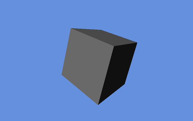
In graphics terms, lighting is the process of modifying color values onscreen to replicate the effect of light illumination. Real time lighting can vastly improve the aesthetic appearance and apparent detail of a scene. Lighting can add depth and texture to an object that would otherwise appear flat.
User Defined Data Types
Constant Buffer
The constant buffer is used for sharing data between your program and the shaders. Constant buffers usually contain data that will be the same regardless of which vertex is currently being rendered. The constant buffer for this sample contains the world matrix for the current model, and camera and lighting data.
Your constant buffer must be separately defined in each HLSL file and in your graphics application. The same elements must be present in each definition, arranged in the same order.
Sample constant buffer definition in a .cpp file:
C++
struct ConstantBuffer
{
  XMMATRIX mWorld;
  XMMATRIX mView;
  XMMATRIX mProjection;

  // Data for two light sources
  XMFLOAT4 vLightDir[2];    // The direction each light is projected in
  XMFLOAT4 vLightColor[2];  // The color of each light
};
The matching definition in an HLSL file:
C++
cbuffer ConstantBuffer : register( b0 )
{
  matrix World;
  matrix View;
  matrix Proj;

  float4 vLightDir[2];
  float4 vLightColor[2];
}
The order of variables in the .cpp file is the same as they are in the HLSL file, but notice that the variables used are different. The constant buffer declaration in your .cpp file must be within namespace DirectX. Use DirectX structs like XMMATRIX and XMFLOAT4. The DirectX structs directly translate to different variables in HLSL: XMMATRIX becomes matrix, and XMFLOAT4 becomes float4.
You can have multiple constant buffers active simultaneously, each must be assigned to its own register. When declaring the constant buffers in your HLSL file, you must declare which register the buffer will be stored in. The first buffer should be placed in register( b0 ), the second buffer should be placed in register( b1 ), and so on.
Vertex
Each point in 3D space is represented by a vertex. The vertex struct is user defined, and may contain any data you specify. In order to render lighting, each vertex requires an XYZ position and a normal vector. Normal vectors are used by the shaders to determine which direction each polygon is facing. The normal vector of a face and the light direction vectors are used to calculate how well illuminated that face is. You may need to generate a unique vertex for each face that touches an individual point.
Sample vertex struct definition:
C++
struct SimpleVertex
{
  XMFLOAT3 Pos;
  XMFLOAT3 Normal;
};
The vertex struct is bound by the same rules as the constant buffer struct: it must be defined within namespace DirectX, and must use DirectX structs like XMMATRIX and XMFLOAT4.
Input Element Description
Your application needs to tell the Vertex Shader how your vertex data is arranged for the systems to interact effectively. The D3D11_INPUT_ELEMENT_DESC struct is used to communicate between systems. Each D3D11_INPUT_ELEMENT_DESC struct defines a single element of your vertex struct, you will need to create an array of them to define the entire struct.
INPUT_ELEMENT_DESC matching the vertex struct defined above:
C++
const D3D11_INPUT_ELEMENT_DESC InputElementDesc[] =
{
  { "POSITION", 0, DXGI_FORMAT_R32G32B32_FLOAT, 0, 0, D3D11_INPUT_PER_VERTEX_DATA, 0 },
  { "NORMAL", 0, DXGI_FORMAT_R32G32B32_FLOAT, 0, 12, D3D11_INPUT_PER_VERTEX_DATA, 0 },
};
HLSL Input/Output
The Vertex Shader input must match the layout of the vertex struct and input element description defined above.
C++
struct VS_INPUT
{
  float4 Pos : POSITION;
  float3 Norm : NORMAL;
};
The Vertex shader output must match the input of the next shader. In this sample, the Vertex Shader passes data directly to the Pixel Shader. The Vertex Shader output is the Pixel Shader input.
C++
struct PS_INPUT
{
  float4 Pos : SV_POSITION;
  float3 Norm : TEXCOORD0;
};
The Pixel Shader is the last stage in the graphics pipeline, and simply outputs an array of 4 floats that represent the color of the pixel.
Initialization
Create the Vertex Shader and Pixel Shader:
Create a Vertex Shader by calling ID3D11Device::CreateVertexShader(). Pixel Shaders are created with ID3D11Device::CreatePixelShader().
C++
DX::ThrowIfFailed( m_d3dDevice->CreateVertexShader( g_vs_main,
  sizeof( g_vs_main ),
  NULL,
  m_VertexShader.GetAddressOf() )
);

DX::ThrowIfFailed( m_d3dDevice->CreatePixelShader( g_ps_main,
  sizeof( g_ps_main ),
  NULL,
  m_PixelShader.GetAddressOf() )
);
Define, Create and Setup the Input Layout:
Define an INPUT_ELEMENT_DESC to facilitate communication between your program and the HLSL Shaders. After defining the element description, you can create the input layout by calling ID3D11Device::CreateInputLayout().
C++
// Create the input layout
DX::ThrowIfFailed( m_d3dDevice->CreateInputLayout( InputElementDesc,
  _countof( InputElementDesc ),
  g_vs_main,
  sizeof( g_vs_main ),
  m_InputLayout.GetAddressOf() )
);
After the input layout has been created, you will need to set it with ID3D11DeviceContext::IASetInputLayout().
C++
// Set as the primary input layout
m_d3dContext->IASetInputLayout( m_InputLayout.Get() );
Define and Create Vertex Buffer:
Store all the vertices for a particular mesh in a single array. Typically mesh vertices are read in from a file, this sample uses a hardcoded cube mesh for readability and descriptive purposes. Notice that each corner of the cube is represented by three vertices with different normal vectors, one for each face touching that corner.
After you have defined an array of vertices, you will need to create a D3D11_BUFFER_DESC struct and a D3D11_SUBRESOURCE_DATA struct. After all three objects are created and initialized, call ID3D11Device::CreateBuffer().
C++
// Create vertex buffer
SimpleVertex vertices[] =
{
  { XMFLOAT3( -1.0f, 1.0f, -1.0f ), XMFLOAT3( 0.0f, 1.0f, 0.0f ) },
  { XMFLOAT3( 1.0f, 1.0f, -1.0f ), XMFLOAT3( 0.0f, 1.0f, 0.0f ) },
  { XMFLOAT3( 1.0f, 1.0f, 1.0f ), XMFLOAT3( 0.0f, 1.0f, 0.0f ) },
  { XMFLOAT3( -1.0f, 1.0f, 1.0f ), XMFLOAT3( 0.0f, 1.0f, 0.0f ) },

  { XMFLOAT3( -1.0f, -1.0f, -1.0f ), XMFLOAT3( 0.0f, -1.0f, 0.0f ) },
  { XMFLOAT3( 1.0f, -1.0f, -1.0f ), XMFLOAT3( 0.0f, -1.0f, 0.0f ) },
  { XMFLOAT3( 1.0f, -1.0f, 1.0f ), XMFLOAT3( 0.0f, -1.0f, 0.0f ) },
  { XMFLOAT3( -1.0f, -1.0f, 1.0f ), XMFLOAT3( 0.0f, -1.0f, 0.0f ) },

  { XMFLOAT3( -1.0f, -1.0f, 1.0f ), XMFLOAT3( -1.0f, 0.0f, 0.0f ) },
  { XMFLOAT3( -1.0f, -1.0f, -1.0f ), XMFLOAT3( -1.0f, 0.0f, 0.0f ) },
  { XMFLOAT3( -1.0f, 1.0f, -1.0f ), XMFLOAT3( -1.0f, 0.0f, 0.0f ) },
  { XMFLOAT3( -1.0f, 1.0f, 1.0f ), XMFLOAT3( -1.0f, 0.0f, 0.0f ) },

  { XMFLOAT3( 1.0f, -1.0f, 1.0f ), XMFLOAT3( 1.0f, 0.0f, 0.0f ) },
  { XMFLOAT3( 1.0f, -1.0f, -1.0f ), XMFLOAT3( 1.0f, 0.0f, 0.0f ) },
  { XMFLOAT3( 1.0f, 1.0f, -1.0f ), XMFLOAT3( 1.0f, 0.0f, 0.0f ) },
  { XMFLOAT3( 1.0f, 1.0f, 1.0f ), XMFLOAT3( 1.0f, 0.0f, 0.0f ) },

  { XMFLOAT3( -1.0f, -1.0f, -1.0f ), XMFLOAT3( 0.0f, 0.0f, -1.0f ) },
  { XMFLOAT3( 1.0f, -1.0f, -1.0f ), XMFLOAT3( 0.0f, 0.0f, -1.0f ) },
  { XMFLOAT3( 1.0f, 1.0f, -1.0f ), XMFLOAT3( 0.0f, 0.0f, -1.0f ) },
  { XMFLOAT3( -1.0f, 1.0f, -1.0f ), XMFLOAT3( 0.0f, 0.0f, -1.0f ) },

  { XMFLOAT3( -1.0f, -1.0f, 1.0f ), XMFLOAT3( 0.0f, 0.0f, 1.0f ) },
  { XMFLOAT3( 1.0f, -1.0f, 1.0f ), XMFLOAT3( 0.0f, 0.0f, 1.0f ) },
  { XMFLOAT3( 1.0f, 1.0f, 1.0f ), XMFLOAT3( 0.0f, 0.0f, 1.0f ) },
  { XMFLOAT3( -1.0f, 1.0f, 1.0f ), XMFLOAT3( 0.0f, 0.0f, 1.0f ) },
};
D3D11_BUFFER_DESC bd;
ZeroMemory( &bd, sizeof(bd) );
bd.Usage = D3D11_USAGE_DEFAULT;
bd.ByteWidth = sizeof( SimpleVertex ) * 24;
bd.BindFlags = D3D11_BIND_VERTEX_BUFFER;
bd.CPUAccessFlags = 0;
D3D11_SUBRESOURCE_DATA InitData;
ZeroMemory( &InitData, sizeof(InitData) );
InitData.pSysMem = vertices;
DX::ThrowIfFailed( m_d3dDevice->CreateBuffer( &bd, &InitData, m_VertexBuffer.GetAddressOf() ) );
After the vertex buffer has been created, set it by calling ID3D11DeviceContext::IASetVertexBuffers().
C++
// Set vertex buffer
UINT stride = sizeof( SimpleVertex );
UINT offset = 0;
m_d3dContext->IASetVertexBuffers( 0, 1, m_VertexBuffer.GetAddressOf(), &stride, &offset );
Define and Create Index Buffer:
The Index buffer determines the order that vertices are rendered in, three indices define a polygon. The index array is typically loaded from the same file that contains the vertices, but this sample uses a hardcoded array for readability.
After you have defined the array of indices, you will need to create a D3D11_BUFFER_DESC struct and a D3D11_SUBRESOURCE_DATA struct to describe the index array. Once all three objects are created and initialized, create the buffer by calling ID3D11Device::CreateBuffer().
C++
// Create index buffer
WORD indices[] =
{
  3,1,0,
  2,1,3,

  6,4,5,
  7,4,6,

  11,9,8,
  10,9,11,

  14,12,13,
  15,12,14,

  19,17,16,
  18,17,19,

  22,20,21,
  23,20,22
};
bd.Usage = D3D11_USAGE_DEFAULT;
bd.ByteWidth = sizeof( WORD ) * 36;        // 36 vertices needed for 12 triangles in a triangle list
bd.BindFlags = D3D11_BIND_INDEX_BUFFER;
bd.CPUAccessFlags = 0;
InitData.pSysMem = indices;
DX::ThrowIfFailed( m_d3dDevice->CreateBuffer( &bd, &InitData, m_IndexBuffer.GetAddressOf() ) );
After the index buffer has been created, set it by calling ID3D11DeviceContext::IASetIndexBuffer().
C++
// Set index buffer
m_d3dContext->IASetIndexBuffer( m_IndexBuffer.Get(), DXGI_FORMAT_R16_UINT, 0 );
Set Primitive Topology:
The primitive topology determines how indices are read from the index buffer. This example uses D3D11_PRIMITIVE_TOPOLOGY_TRIANGLELIST.
C++
// Set primitive topology
m_d3dContext->IASetPrimitiveTopology( D3D11_PRIMITIVE_TOPOLOGY_TRIANGLELIST );
Create Constant Buffer
Describe the constant buffer with a D3D11_BUFFER_DESC, then create the constant buffer by caling ID3D11Device::CreateBuffer().
C++
// Create the constant buffer
bd.Usage = D3D11_USAGE_DEFAULT;
bd.ByteWidth = sizeof(ConstantBuffer);
bd.BindFlags = D3D11_BIND_CONSTANT_BUFFER;
bd.CPUAccessFlags = 0;
DX::ThrowIfFailed( m_d3dDevice->CreateBuffer( &bd, nullptr, m_ConstantBuffer.GetAddressOf() ) );
Initialize the View and Projection Matrices:
The view matrix and projection matrix are necessary for any 3D application. The view matrix represents the position and orientation of the camera, for translating objects from World coordinates to View coordinates. The projection matrix helps determine which objects appear onscreen, and where onscreen to draw those objects. The projection matrix is where you define the Field of View(FOV), aspect ratio, and draw distance for your game.
C++
// Initialize the view matrix
XMVECTOR Eye = XMVectorSet( 0.0f, 1.0f, -5.0f, 0.0f ); // The position of the camera
XMVECTOR At = XMVectorSet( 0.0f, 1.0f, 0.0f, 0.0f );   // The position that the camera is looking at
XMVECTOR Up = XMVectorSet( 0.0f, 1.0f, 0.0f, 0.0f );   // The up vector for the camera
g_View = XMMatrixLookAtLH( Eye, At, Up );

// Initialize the projection matrix
g_Projection = XMMatrixPerspectiveFovLH( XM_PIDIV2, 1920 / (FLOAT)1080, 0.01f, 100.0f );
Rendering
Update the Constant Buffer:
Constant buffers enable you to provide data from your program to the Vertex Shader. Before you can draw a frame, you need to update the constant buffer data with any changes that occurred during your update phase. To update a constant buffer, create a temporary constant buffer and populate it with the desired data. Call ID3D11DeviceContext::UpdateSubresource() to copy the data from the temporary buffer to the actual constant buffer.
C++
// Update matrix and lighting variables
ConstantBuffer cb1;
cb1.mWorld = XMMatrixTranspose( g_World );           // Updated world matrix for current model
cb1.mView = XMMatrixTranspose( g_View );             // Updated view matrix
cb1.mProjection = XMMatrixTranspose( g_Projection ); // Updated projection matrix
cb1.vLightDir[0] = vLightDirs[0];                    // Updated light direction vectors
cb1.vLightDir[1] = vLightDirs[1];
cb1.vLightColor[0] = vLightColors[0];                // Updated light colors
cb1.vLightColor[1] = vLightColors[1];
m_d3dContext->UpdateSubresource( m_ConstantBuffer.Get(), 0, nullptr, &cb1, 0, 0 );
Set Shader Pointers and Constant Buffers:
DirectX needs to know which shaders you are going to use before it can render a frame. You may be using multiple shaders for different rendering properties. For example, transparent objects may use a different pixel shader than dull or reflective objects. You will need to set any shaders that you are going to use, as well as setting the constant buffers for those shaders. For this sample we are using a Vertex Shader and a Pixel Shader, and both shaders share a single constant buffer. Use ID3D11DeviceContext::VSSetShader() to set the Vertex Shader and ID3D11DeviceContext::VSSetConstantBuffers() to set the constant buffer. Use ID3D11DeviceContext::PSSetShader() to set the Pixel Shader and ID3D11DeviceContext::PSSetConstantBuffers() to set the constant buffer.
C++
// Set Shaders and Constant Buffers
m_d3dContext->VSSetShader( m_VertexShader.Get(), nullptr, 0 );
m_d3dContext->VSSetConstantBuffers( 0, 1, m_ConstantBuffer.GetAddressOf() );
m_d3dContext->PSSetShader( m_PixelShader.Get(), nullptr, 0 );
m_d3dContext->PSSetConstantBuffers( 0, 1, m_ConstantBuffer.GetAddressOf() );
Draw Models
Now that everything is set up, we can begin drawing objects. Use ID3D11DeviceContext::DrawIndexed() to render an object. Be sure to enter the correct number of indices, or the models will not render properly.
C++
// Render the cube
m_d3dContext->DrawIndexed( 36, 0, 0 );        // 36 vertices needed for 12 triangles in a triangle list
The Vertex Shader
The Vertex Shader takes vertices in model space and translates them into world space, then view space, and finally projection space. World space determines where the vertex is relative to the game world. View space determines where the vertex is relative to the camera. Projection space determines where the vertex appear on a 2D plane that represents the screen.
The normal vector only gets translated from model space to world space. The normals need to stay in world space because the lighting vectors are in world space. If the lighting vectors and vertex normals are translated to different spaces, then we cannot calculate how to properly illuminate the polygons.
C++
PS_INPUT main( VS_INPUT input )
{
  PS_INPUT output = (PS_INPUT)0;
  output.Pos = mul( input.Pos, World );  // Translate Vertex from model space to world space
  output.Pos = mul( output.Pos, View );  // Translate Vertex from world space to view space
  output.Pos = mul( output.Pos, Proj );  // Translate Vertex from view space projection space

  // Translate Normal Vector from model space to world space
  output.Norm = mul( float4( input.Norm, 0.0f ), World ).xyz;
  output.Norm = normalize(output.Norm);

  return output;
}
The Pixel Shader
The Pixel Shader examines every pixel and sets the color of those pixels. The pixel shader in this sample starts with the color black, and then lightens the color based on the result of an NdotL lighting calculation. NdotL lighting compares the direction of the normal vector and light vector.
If the normal vector has the same orientation as the light vector, then the surface is facing away from the light source and is in shadow. Conversely, if the normal vector is facing the opposite direction as the light vector, then the light is shining directly on the surface, and it should be well illuminated.
C++
float4 main( PS_INPUT input) : SV_Target
{
  float4 finalColor = 0;

  // do NdotL lighting for 2 lights
  for(int i=0; i<2; i++)
  {
    finalColor += saturate( dot( (float3)vLightDir[i],input.Norm) * vLightColor[i] );
  }
  finalColor.a = 1;
  return finalColor;
}