Getting Started with HDR
Claude Marais, Xbox Advanced Technology Group
Updated November 14th 2016
In this topic
Make changes to the render pipeline
Introduction
Ultra High Definition (UHD) consumer TVs include a number of features that can enhance the visual quality of a game. One of these features is the capability to display images in high dynamic range (HDR). For a game to take advantage of HDR, render pipeline changes are required. This white paper outlines a number of high level steps that can help make these changes to successfully implement HDR in a game. It focuses mainly on engineering changes and on the HDR aspect of UHD TVs. Wide color gamut (WCG) will be discussed in a separate white paper.
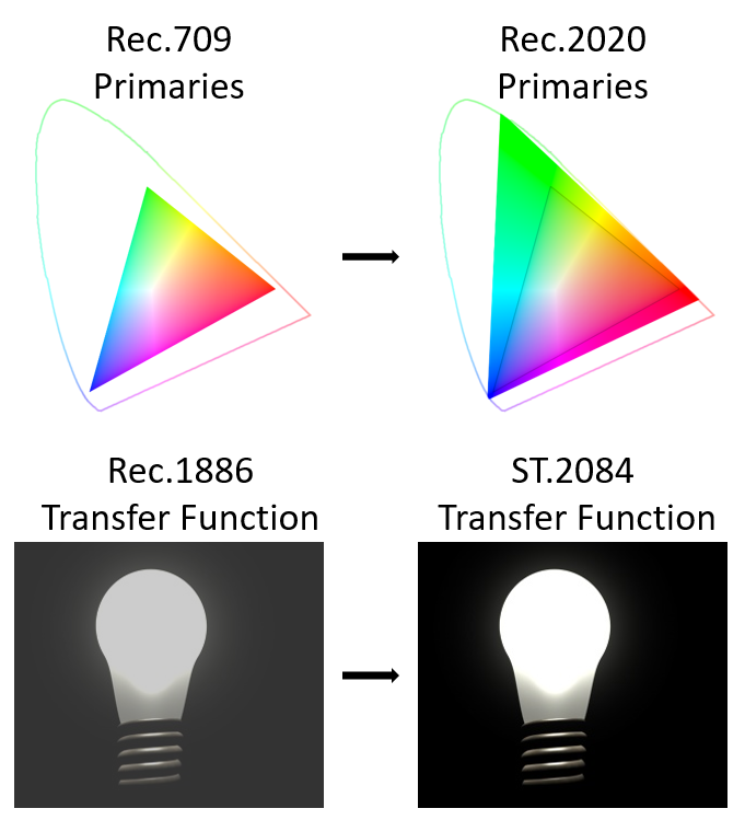
Because Xbox One supports HDR10, all references to implementing HDR in this white paper are only applicable to HDR10. HDR10 is a standard that uses 10 bits to encode an HDMI signal by using the color primaries of Rec.2020 with the ST.2084 transfer function. Rec.2020 is a larger color space than Rec.709, and the ST.2084 transfer function allows for the display of many more details in dark and bright areas compared to the Rec.1886 transfer function.
Figure 1 – A visual representation of the larger Rec.2020 color space and ST.2084 being able to display more details in the dark and bright areas.
A recipe for success
Follow these steps to help you successfully implement HDR in your game:
- Buy an HDR TV
- Set up your dev kit
- Learn about HDR
- Render SDR on an HDR TV
- Get initial HDR results
- Make changes to the render pipeline
Buy an HDR TV
Buying an HDR TV is the first step towards implementing HDR in a game. Make sure that the TV supports HDR10. TVs branded as “UHD Premium” are guaranteed to work with the Xbox One S console. Because HDR is a relatively new feature, firmware updates are available more frequently than usual, so remember to do a firmware update after buying an HDR TV. Some TV settings to consider are the following.
| Feature | Setting |
|---|---|
| HDMI UHD Color HDMI ULTRA HD Deep Color HDMI Ultra HD |
Enable |
| Contrast | 98-100 |
| Sharpness | 0 |
| Auto image enhancements (for example: dynamic contrast, noise reduction, motion enhancement) | Disable |
Set up your devkit
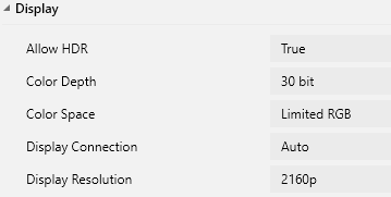
The Xbox One S console supports HDR and 4K video output. Setting the Development Kit (devkit) to 4K video output allows it to upscale images to 4K by using its hardware scaler. Also, set the devkit to output 30 bit (10-bit per channel). Because HDR10 encodes a 10-bit signal, setting the devkit to output 24 bit (8-bit per channel) will show color banding.
Figure 2 – Display settings from the Xbox One Manager tool.
Learn about HDR
Samples and white papers are a good starting point to learn about HDR. Specifically, the SimpleHDR sample can be used to visualize what bright values (values higher than white) look like on an HDR TV. It also shows where bright values are represented on the ST.2084 transfer function, introduces the terminology of paper white, and correlates rendered HDR scene values to actual brightness values measured in nits, with nits being a unit to measure luminance as candela per square meter (cd/m^2). For example, a rendered value of 10.0 will measure 1,000 nits with a colorimeter when using 100 nits as paper white.
The following is a list of white papers, presentations, and samples to help you better understand HDR on Xbox One.
- HDR on Xbox One white paper
- HDR Display Mapping white paper
- An Introduction to HDR and Wide Color Gamut on UHD Displays: pptx and video (Xfest 2016)
- Samples
- SimpleHDR sample
- HDRCalibration sample
- HDRDisplayMapping sample
Render SDR on an HDR TV
From this point forward, it is assumed that the reader has worked through the proposed educational material, and has a fair understanding of HDR terminology.
The first code changes towards getting started with HDR shouldn’t actually be to render HDR, but rather to be able to render the game’s existing standard dynamic range (SDR) tone mapped image correctly on an HDR TV. When just outputting the SDR swap chain buffer to an HDR TV, the image will look wrong. Colors will be over-saturated and displayed as bright as what the TV is capable of displaying. For the SDR image to be correctly displayed on an HDR TV, the image will first need to be converted to HDR10. This can be done by adding a pixel shader right before the D3D Present call to do the HDR10 conversion.
Figure 3 – A generic render pipeline that produces an SDR image. Green indicates HDR values and blue indicates SDR values. Color grading and SDR tone mapping are often combined into a single lookup table.
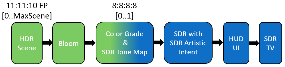
Figure 4 – The same generic render pipeline as in Figure 3, but adding an HDR10 conversion right at the end so that the image can be displayed correctly on an HDR TV.
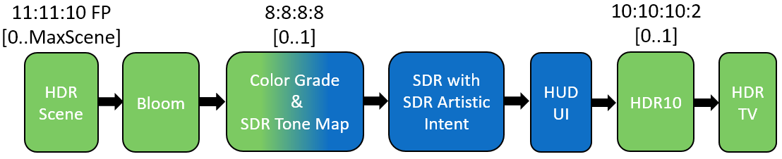
This approach ensures that the pixel shader for the HDR10 conversion is correctly implemented and that you have a baseline to work with when doing comparisons between images. This is a very simple process because no changes in the existing render pipeline or content are required. At this point, the game on an SDR TV should look fairly similar to that on an HDR TV in terms of color, contrast, and brightness. If it doesn’t, refer to the Troubleshooting section at the end of this white paper.
Get initial HDR results
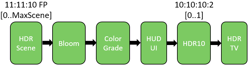
A tone map operator can be used to adjust the look of an image and map colors into a different range. Therefore, games use an SDR tone map operator to map HDR scene values in a range of [0..1] so that the game can be displayed on an SDR TV. Because an HDR TV can actually display HDR values, the easiest way to get initial HDR results would be to simply not apply the game’s SDR tone map operator. This lets you keep using the HDR scene values right through to the end of the render pipeline. The initial results will be far from optimal because details in the bright areas will be clipped, but they will give an idea of the potential increase in visual quality that comes with HDR.
Figure 5 – The same render pipeline as in Figure 4, but with the SDR tone map operator removed.
Make changes to the render pipeline
Changes to the render pipeline will be required. This section discusses some of the options.
HDR mastered vs. SDR mastered
Game content is created with a certain artistic intent; that is, after the scene is rendered, adjustments can be made so that the image looks a certain intended way (for example, add contrast or make the image look warmer). In most games, artistic intent is achieved by applying color grading and a tone map operator. Currently, game content is created on and adjusted to look great on an SDR TV. We’ll refer to this as SDR mastered, because it has the SDR artistic intent. The ideal scenario is when content is created on and adjusted to look great on an HDR TV. We’ll refer to this as HDR mastered, because it has the HDR artistic intent. When it comes to making changes to the render pipeline, the most significant decision will be to decide between SDR or HDR artistic intent.
HDR mastered
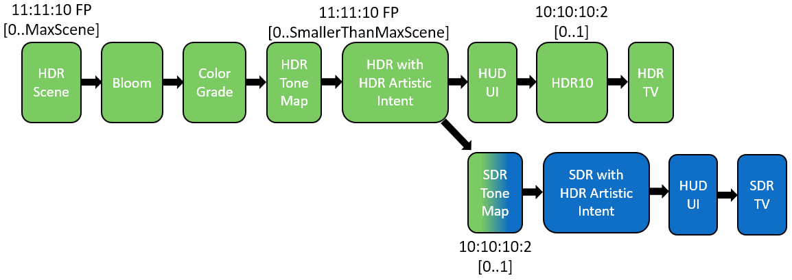
Because an HDR TV can display the actual rendered HDR scene values, content can be created and adjusted to look great on an HDR TV. A tone map operator isn’t just for mapping HDR scene values from the range of [0..MaxScene] to [0..1], but is part of creating artistic intent. Therefore, even when we can display the HDR scene values on an HDR TV, we still need color grading and a tone map operator to adjust artistic intent. We’ll refer to the tone map operator that adjusts HDR artistic intent and maps HDR scene values into a smaller HDR range as HDR tone mapping.
Figure 6 shows how color grading and an HDR tone map operator result in an HDR mastered image with HDR artistic intent. Traditionally, an SDR tone mapper would be subjectively created to display the rendered HDR image because we didn’t have a means to display the actual HDR values. In this scenario, when rendering an SDR image for an SDR TV, an SDR tone map operator needs to be created to closely match the image on an HDR TV, thus creating an SDR image with HDR artistic intent. This is different from the traditional SDR image with SDR artistic intent as seen in figure 4.
There are some challenges with this approach. Most people creating and reviewing content will need to have an HDR TV. Also, all post-processing techniques applied after a traditional SDR tone map operator, such as FXAA, will need to be adjusted to operate on the range of [0..MaxScene] HDR values, rather than [0..1]. Color grading now also has to be done on floating point HDR values.
Figure 6 – Render pipeline for HDR mastered.
SDR mastered
A good stepping stone towards HDR with HDR artistic intent is to implement HDR with SDR artistic intent—that is, the image is mastered as SDR, and then remastered as HDR. In this scenario, content is created and tuned to look great on an SDR TV. After the tone mapped SDR image is rendered with SDR artistic intent, the HDR scene values can be reconstructed by using an inverse tone mapper. We can think of the SDR tone map operator as a way to compress HDR scene values, and the reconstruction as a way to decompress the HDR scene values. The reconstructed HDR values will not be the same as the original HDR scene values because they were reconstructed from an SDR image with SDR artistic intent. It is also important to note that if HUD or UI elements are rendered during the scene rendering, that is, not after scene rendering, these elements will get reconstructed to the maximum brightness of the TV, which will be very fatiguing to the consumer.
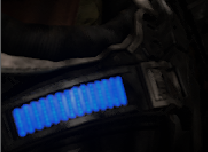
Figures 8 to 11 show an example of how SDR artistic intent can be different from HDR artistic intent. Although this is not the ideal scenario, it does allow for adding HDR to your game with very few changes to your existing SDR render pipeline. It also allows for development and content creation to be done by using SDR TVs because the HDR image will look similar on an SDR TV, but the bright areas will now actually be displayed as bright.
Figure 7 shows an optional HDR tone map operator that could be useful to adjust contrast in the HDR image.
Figure 7 – Render pipeline for SDR mastered.
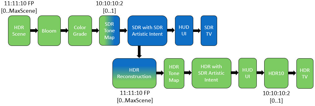
Figure 8 – Rendered HDR scene values showing bright blue lights. HDR with HDR artistic intent will display the blue as bright blue on an HDR TV. To show the range of brightness in the image, the mid-tone colors are displayed as very dark.
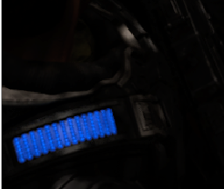
Figure 9 – Tone mapped SDR image with SDR artistic intent. The bright blue lights cannot be displayed as bright blue on an SDR TV, so the SDR tone mapper introduces a change in color.
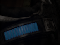
Figure 10 – HDR reconstruction using luminance of the color channels results in an HDR image with SDR artistic intent. Even though the colors are different from the original HDR image in Figure 8, the brightness is similar to that of the original HDR image, and it does match the SDR artistic intent from Figure 9. Therefore, as the tone mapped SDR image is tuned and adjusted to look great on an SDR TV, the colors in this reconstruction method will always match the SDR image.
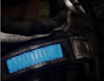
Figure 11 – HDR reconstruction per color channel results in an HDR image with different SDR artistic intent, almost described as a blend between the original HDR image in Figure 8 and the tone mapped SDR image in Figure 9. Therefore, as the tone mapped SDR image is tuned and adjusted to look great on an SDR TV, the colors in this reconstruction method will not always match the SDR image. However, the more saturated colors result in better contrast and a more natural looking image.
HUD and UI
HUD and UI elements need to be displayed in the range of [black..white]. HDR Xbox One games are required to output an HDR swap chain buffer as well as an SDR swap chain buffer to be used for Game DVR and screenshots. Render pipeline changes are required to render HUD and UI elements correctly for presenting both swap chain buffers. The following describes possible solutions.
Tone mapped HUD/UI
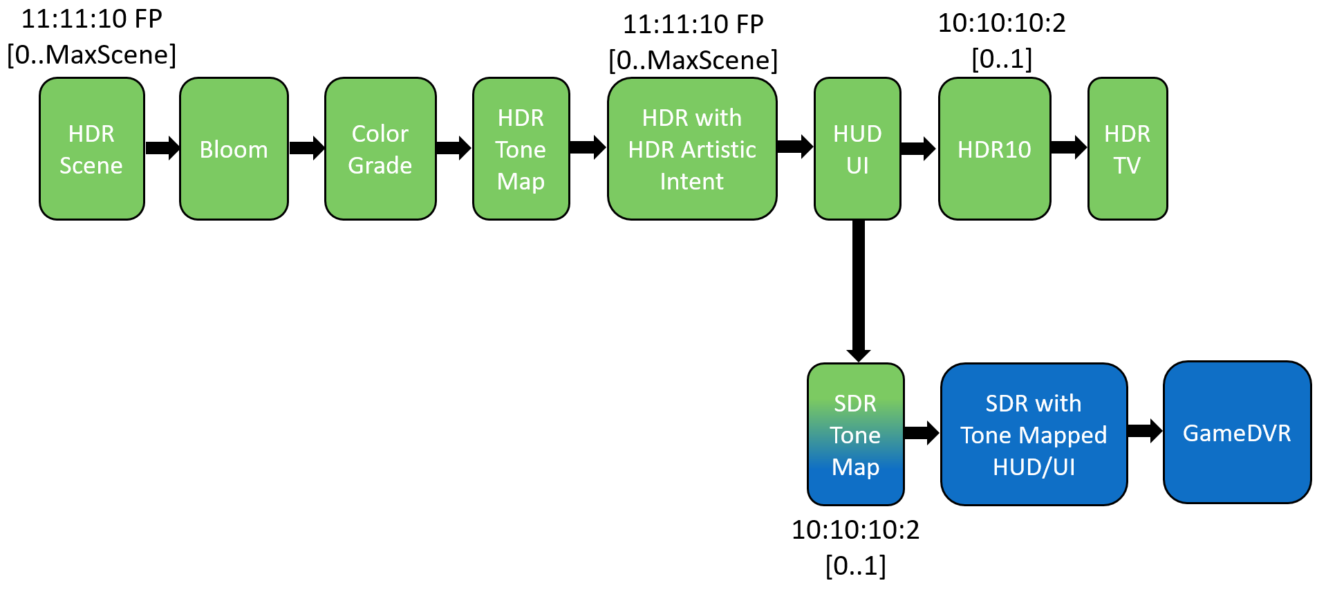
A simple way to get started is to keep the render pipeline very similar to SDR by rendering the HUD/UI elements only once, directly into the HDR buffer. In this scenario, the HUD/UI elements will be slightly dimmer for GameDVR and screenshots because they will be included in the SDR tone map operation, as illustrated in figure 12. To compensate for this, you can render the HUD/UI elements a little brighter than the scene. For example, render the scene at 120 nits, but the HUD/UI at 200 nits.
Figure 12 – Render pipeline with HUD and UI elements rendered to the HDR buffer and included in the SDR tone map operation.
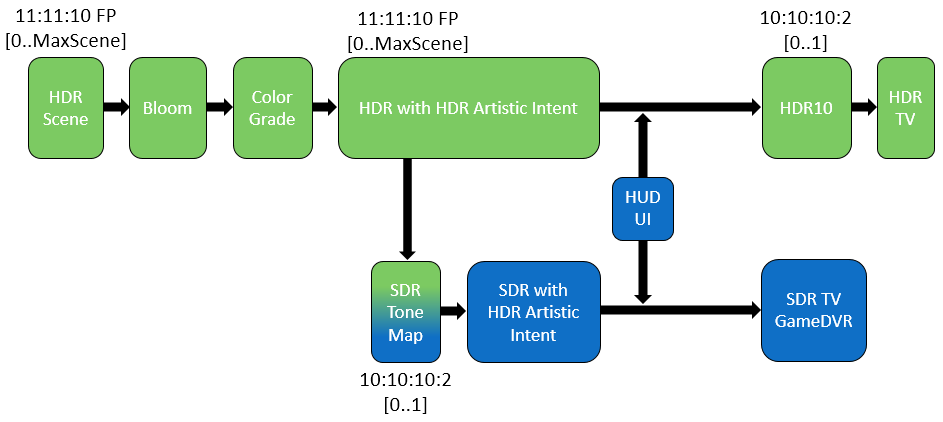
Multiple render targets
In this scenario, the pixel shaders for HUD and UI elements write out to two render targets, one for HDR and one for SDR. One advantage of this approach is that there are no restrictions on the complexity of alpha blending; for example, additive and modulate simply just work. But HUD and UI elements are restricted to be rendered at the same resolution as the scene. It is also more challenging to precisely measure the performance impact because it will vary by the number of elements rendered and how many pixels they cover.
Figure 13 – Render pipeline using multiple render targets for rendering HUD and UI elements.
Separate buffer composited
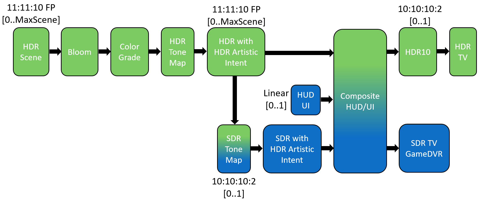
In this scenario, the HUD and UI elements are rendered to a separate buffer and composited onto the HDR and SDR buffers with a single pixel shader. This does allow for the HUD and UI elements to be rendered at a higher resolution than the scene, but complex blend modes can be challenging. It also does allow for easily measuring the performance implications because it’s just a single pixel shader to analyze.
Figure 14 – Render pipeline using a separate buffer to composite HUD and UI elements.
Render HUD/UI twice
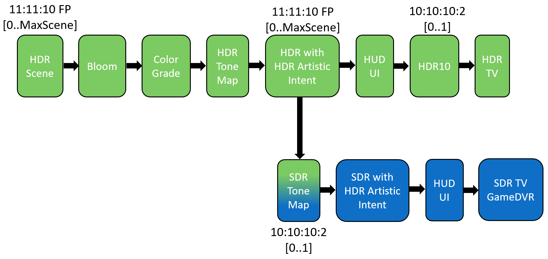
Another option is to simply render HUD and UI elements twice, once for the HDR buffer and once for the SDR buffer. This scenario is very similar to using multiple render targets, but has the advantage of not having to modify pixel shaders for HUD and UI. One thing to keep in mind is that the pixel shaders for HUD and UI elements have to write out linear values for the HDR buffer.
Figure 15 – Render pipeline with HUD and UI elements being rendered twice.
Tips
-
When just getting started with HDR, it’s a good idea to ignore display mapping to simplify things. However, we highly recommend that you implement display mapping beyond the “getting started” stage. HDR is not only about how bright you can render things, but also about being able to see details in the dark areas and the bright areas that cannot be seen on an SDR TV. Display mapping ensures that details in the bright areas are not lost because the TV cannot display values brighter than what it is capable of.
-
We recommend using paper white at 120 nits for the scene and 200 nits for HUD/UI. The game’s HUD/UI will then be just as bright as the Xbox One Home UI, which is 200 nits. Do not set the paper white value for the scene too high, or the game will sacrifice too much of the potential range of the HDR TV for a brighter SDR range. This can result in an image looking more like “medium” dynamic range rather than “high” dynamic range. This scenario normally happens when adjusting paper white higher so that the values in the SDR range on an HDR TV match the brightness on an SDR TV. The image on an SDR TV will look brighter than the SDR range of the image on an HDR TV because the SDR TV will try to use its full potential brightness to display the SDR image, whereas the HDR TV will display the actual HDR values more correctly. Implement the pixel shader that does the HDR10 conversion in such a way that paper white can easily be adjusted.
-
When doing visual comparisons, always use color calibrated TVs with all the TV’s auto image enhancements disabled—for example, dynamic contrast.
-
Compare HDR and SDR images on the same TV. This can be done in one of three ways: 1) use “xbconfig AllowHDR <true false>”, 2) toggle the Allow HDR setting in the Xbox One Manager tool, or 3) toggle the Xbox One’s Allow HDR option in Advanced video settings. In the scenario where the game is started with HDR disabled on the Xbox One console, the TrySetHdrModeAsync API will simply return FALSE, as if it were attached to an SDR TV, thus running the game in SDR mode on an HDR TV. The more interesting scenario is to launch the game in HDR mode and then toggle the game to SDR, which will then present the game’s SDR GameDVR swap chain buffer. This will give a fair comparison between HDR and SDR, because you’re observing both modes on the same TV. Note that most TVs have a separate set of color controls for HDR and SDR. -
Buy different HDR TVs, preferably from various manufacturers and with different panel types—for example, OLED vs. LCD. Different TVs will have different maximum brightness levels and will display very bright values in different ways. So it’s important to test the game’s implementation of display mapping on a variety of TVs.
-
Compare HDR on different HDR TVs at the same time, by using a 4K HDMI 2.0 splitter. This will allow you to run the game from a single Xbox One console, but seeing the image on different HDR TVs at the same time.
-
Use a colorimeter to objectively compare colors. For example, comparing a red block rendered at 100 nits could be perceived as a different color when the same red block is rendered at 1,000 nits. In this example, the color values didn’t change, only the brightness, so a colorimeter will objectively measure the two red blocks as the same color values. Calibration color cards could also be useful, but cannot objectively compare the same color of very different brightness levels.
-
When comparing SDR and HDR images, it’s worth taking screen shots of the SDR image at certain points in the game. This way you don’t need to run the game on two devkits simultaneously; simply compare the screenshots on the PC monitor to the HDR image on the HDR TV.
- Even when rendering an HDR10 and a Game DVR swap chain buffer, the Xbox One console will always display the Game DVR swap chain buffer when no HDR TV is attached. However, there are scenarios where it is useful during development to be able to display the HDR10 swap chain buffer, even if no HDR TV is attached. For example, because an HDR reference monitor is not a TV, it is seen as an SDR TV by the TrySetHdrModeAsync API, so the SDR swap chain buffer will be displayed. Also, scenarios where no TVs are attached, such as test labs or using the Xbox One Manager’s Remote feature, will have a similar behavior. To be able to force the Xbox One console to display the HDR10 swap chain buffer, use the following:
xbconfig displayconnection=hdmi2.
-
Clearly define shader input and output variables as linear or sRGB. All shader output to an HDR buffer needs to be linear. Most games write out linear values and have the hardware do the sRGB encoding and decoding. However, some games manually encode sRGB in the pixel shader. In this case, it is easy to make mistakes if the shader input and output variables are not clearly marked as linear or sRGB.
-
Implement the render pipeline so that it is easy to switch between SDR and HDR, even if it doesn’t get displayed correctly. This is very useful for doing performance investigations between SDR and HDR without having to run the game several times and get the exact same scene in the game.
-
Implement a split screen visualization to show the game as HDR and SDR. This is very useful for debugging, demos, and reviews.
-
Implement an option to visualize HDR values in the scene, for example, display all values above 1.0f as purple. This is useful to focus your eyes on the image when looking for changes in the HDR image.
Troubleshooting
Colors look too bright and over-saturated
The SDR image is displayed on an HDR TV without having been converted to HDR10.
Colors look slightly different on an HDR TV than on an SDR TV
Small differences in the same rendered color between HDR and SDR are expected. Even though a color is measured with a colorimeter to be exactly the same on a SDR and HDR TV, the color might be perceived as different, because the perception of colors changes when other colors around it change in brightness and contrast. This is referred to as the “color appearance model.” Colors should be similar if the same color grading is used. Small differences might be visible because of TV settings and different TV models. Also, because no TV at this point in time can actually display the full color range of Rec.2020, TVs have to do a color mapping by using the input Rec.2020 color values to what it is capable of displaying. But, in the case of displaying SDR content with Rec.709 colors, the differences should be very minor. If the colors look similar, but different enough to notice, it might not be a bug in your code, but rather the TV causing the difference. The following steps might help identify the problem:
- Use an HDR reference monitor.
- Color calibrate the TVs.
- Update TV firmware.
- Render primary colors as a test image and objectively measure with a colorimeter.
- Buy two HDR TVs of the exact same model: one for SDR and one for HDR.
Colors on an HDR TV look very different from those on an SDR TV
When colors look very different, it could be a bug introduced in a pixel shader with regard to rendering non-linear values into an HDR buffer that expects linear values. For example, when the pixel shader encodes sRGB manually, alpha blending is done by the hardware on non-linear colors, but by using a linear alpha value, such as blendedColor = HWBlend(srgbColor.rgb, linearColor.a). Because the SDR content was created to look correct using non-linear blending, using the correct linear blending will look different, such as blendedColor = HWBlend(linearColor.rgb, linearColor.a). One way to compensate for this difference is to use a non-linear alpha value, that is, blendedColor = HWBlend(linearColor.rgb, srgbColor.a). Using the PIX shader debugger and clearly marking shader input and output variables as linear or sRGB can help identify the problem.
The SDR image looks brighter than the HDR image
It is expected that the SDR image will look brighter than the HDR image. This is because the SDR image is displayed using the maximum brightness of the SDR TV, while an HDR TV displays the HDR image more correctly in the rendered range of brightness values. How bright white is on an SDR TV varies between SDR TVs, and even varies on the same TV between different display modes, such as Game mode and Movie mode. For example, an SDR TV’s Movie mode might use 120 nits for paper white, because movies are normally watched in a darker environment. But Sports mode might be 220 nits because it is normally used during the day time. We recommend using paper white values of 120 nits for the scene and 200 nits for the HUD/UI, but it is also convenient to implement the pixel shader that does the HDR10 conversion in such a way that the definition of paper white can easily be adjusted to be comparable to the brightness of any SDR TV.
The SDR image has more contrast than the HDR image
The two major things influencing a game’s image contrast are a soft toe introduced at the bottom of a tone map operator, and a consumer adjustable value used in a power function, normally referred to as brightness or display gamma. The display gamma option is the calibration image where the consumer adjusts a slider to not see a logo and barely see a logo. Experiment with changing the display gamma while the game is in HDR mode. Figures 6 and 7 show where an HDR tone map operator can be included in the render pipeline, which can be used to adjust contrast for the HDR image. It is important to note that the SetGammaControl API should not be used for HDR rendering.
If a game manually encodes sRGB in the pixel shader at the point when sampling the buffer with the tone mapped SDR image (for example, when reconstructing the HDR values), the pixel shader has to linearize the values manually. When using the standard operation for sRGB to linear, the contrast will be lost. Using a power function of 2.2 will keep the contrast, that is, LinearColor = pow(SampledSRGBColor, 2.2), because this would more correctly simulate how the hardware would sample an sRGB texture.
Color banding is worse than on an SDR TV
Check that the Xbox One console video output is set to 30 bit (10-bit per channel).
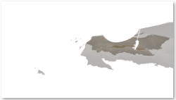
If that doesn’t fix the problem, use the PIX tool to find out where in the render pipeline the banding is introduced. For example, if a game simply changes the format of the back buffer from R8G8B8A8 to R10G10B10A2 to accommodate 10-bit HDR values, the use of the alpha channel becomes very limited. If particles are rendered using an alpha channel, severe banding will be noticeable because there are now only 2 bits of precision for the alpha channel.
Figure 16 – These two images were rendered with the same shaders, geometry, and draw calls, but the back buffer format on the left is R8G8B8A8, while the format on the right is R10G10B10A2.
| R8G8B8A8 | R10G10B10A2 |
|---|---|
 |
 |
Visual artifacts in the dark values are noticeable
Visual artifacts might be visible in darker areas of the image, such as noise and color banding. The main reason for this is because the ST.2084 transfer function designates almost 30% of its precision to dark values in the range of [0..10] nits, which is a lot more than the Rec.1886 transfer function. It is therefore not unreasonable to think that content created by using an sRGB PC monitor or Rec.709 SDR TV will look differently in the dark areas on an HDR TV.
Figure 17 – The image on the left shows a texture displayed in the range of [0 .. 1.0]. The texture appears to be 100% black on an SDR TV. On the right, the same texture is displayed in the range of [0 .. 0.012], which shows noise and color banding not visible on an SDR TV.
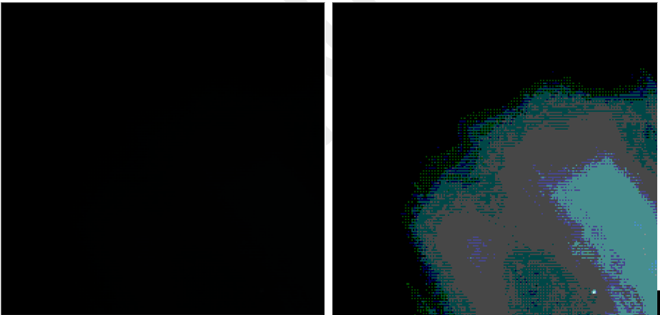
Using the ST.2084 transfer function, the values in the texture shown in Figure 17 will be displayed at the brightness of 2.35 nits, using 200 nits as paper white, which might be visible on an HDR TV. The following could help with visual artifacts:
- Apply dithering to help hide the color banding artifacts
- Create content using an HDR TV.
- Adjust the HDR tone map operator to darken the dark values.
- A simple power function can darken the dark values, for example, Color = pow(Color, 1.1f). Applying this example to the scenario in Figure 17, the brightness of 2.35 nits will be darkened to 1.5 nits, which will be more difficult to see on an HDR TV.
- For content not going through a tone map operator, for example loading screens, values in the range of [0..2] nits could be clipped to 0 nits or, a soft toe in the range of [0..2] nits could be applied to the ST.2084 transfer function.
Beyond getting started
This section discusses a few final things that should be considered.
To get the most out of display mapping, the game needs to know what the perceived brightness of the attached HDR TV is, which in most cases will be different from the advertised maximum brightness of the TV (see the HDR Display Mapping white paper and sample). The game will therefore have to render a calibration image, similar to the display gamma image, to determine the perceived maximum TV brightness.
For example, render an image with an HDR value of 100. Using paper white as 100 nits, this will have the TV try to display 10,000 nits. Because the TV won’t be capable of displaying 10,000 nits, the TV will naturally clip the brightness to what it is capable of displaying, for example 1,100 nits. Next, render another image on top of the first image so that the consumer can adjust the brightness to match the perceived brightness of the first image. At the point where the consumer cannot distinguish between the two images, the maximum perceived brightness has been established, and can be used in display mapping.
Content needs to be reviewed and adjusted to fully take advantage of HDR. In some cases, it might be a relatively small amount of work, especially if the game is already using physical based rendering (PBR). Important things to review are HDR sky boxes, materials that emit light, and materials that reflect light. Some HUD and UI elements might make sense to render as HDR, for example, a bright red warning or damage indicator.
Video playback during introduction screens and cut scenes can currently only be encoded as 8 bit. Therefore, HDR content cannot be recorded for video playback. There are several solutions to this problem.
-
Record the video as an 8-bit encoded tone mapped SDR image. At runtime, play it back as SDR converted to HDR10. The video will look correct, but just not bright. Visual artifacts might be visible due to quantizing to 8 bits, which could be hidden by adding dithering.
- At recording time, quantize the floating point HDR values to 10:10:10:2 by applying a compression algorithm. Then encode the 10:10:10:2 as 8:8:8:8. At runtime, decode the 8:8:8:8 image to 10:10:10:2 and decompress the values to floating point HDR values. This compression could be as simple as using a Reinhard tone map operator:
- compressed = uncompressed / (1 + uncompressed)
- uncompressed = compressed / (1 – compressed)
- Record a 10:10:10:2 tone mapped SDR video encoded as 8:8:8:8. At runtime, the video can be decoded into a 10:10:10:2 tone mapped SDR image. At this point, the image should be the same as if the game had rendered it with SDR artistic intent, and HDR reconstruction can be applied and converted to HDR10. The results are better than just SDR playback, but some detail in the bright areas might be lost. As with the render pipeline for SDR mastered, this is a good stepping stone towards 10-bit encoded HDR video playback.
- Encode the recorded image as 8:8:8:8, but encode luminance separately from the chroma.
- Use real-time rendered scripted cut scenes instead of prerecorded videos.
Summary
For a game to take advantage of the capabilities of an HDR TV, render pipeline changes and possible content changes are required. Buying the right HDR TV is an important starting point. When it comes to making render pipeline changes, the most significant decision will be to decide between SDR or HDR artistic intent. If the game has to ship within a short amount of time, we recommend that you use the SDR mastered approach.
References
- UHD Color for Games (PDF)
- Implementing HDR in “Rise of the Tomb Raider”
- HDR Programming
- High dynamic range television for production and international programme exchange
- ST 2084:2014 Specification: High Dynamic Range Electro-Optical Transfer Function of Mastering Reference Displays
- HDR on Xbox One white paper
- HDR Display Mapping white paper
- An Introduction to HDR and Wide Color Gamut on UHD Displays: pptx and video (Xfest 2016)
- Samples
- SimpleHDR sample
- HDRCalibration sample
- HDRDisplayMapping sample