Caches and Coherency on the Xbox One GPU
With the introduction of fast object semantics contexts and asynchronous compute contexts in DirectX 12, the responsibility for managing resource hazards is in the hands of title developers. Because the Xbox One GPU requires explicit synchronization when data is produced through one type of cache or DMA and then is consumed through another cache or DMA, it is especially important to understand the different mechanisms of synchronization on the GPU.
This topic looks at the GPU as a “pipeline” and describes data coherency and synchronization in terms of moving through the pipeline. It will be especially useful for graphics programmers who want to get correct and performant rendering out of DirectX 11.X fast object semantics contexts and DirectX 12.
Note If you are not yet familiar with the Xbox One GPU’s cache structure, we recommend that you first read the GPU cache documentation on XGD.
In this topic:
Introduction
The Xbox One GPU requires explicit synchronization when data is produced through one type of cache or DMA and then is consumed through another cache or DMA. With the introduction of fast semantics contexts and asynchronous-compute contexts in DirectX 11.X, title developers are now responsible for managing resource hazards. This makes it especially important to understand the different mechanisms of synchronization on the GPU.
DirectX 12 also removes hazard tracking from the API. The abstraction on DirectX 12 is a step higher than it is on DirectX 11.X, but understanding low-level GPU synchronization mechanisms is important on DirectX 12, too.
GPU synchronization
The Xbox One GPU has eight graphics contexts, seven of which are available for games. Loosely speaking, a sequence of draw calls that share the same render state are said to share the same context. Dispatches don’t require graphics contexts, and they can run in parallel with graphics work.
Generally, two concepts are involved in synchronizing the GPU: pipelining and caches.
On a very basic level, a GPU can be thought of as a pipeline in which draw calls and compute-shader dispatches enter from the command processor and retire after they have been fully executed. Even though draws and dispatches can run concurrently on the GPU, they don’t overtake each other and always retire in order.
It’s especially important to know two things about pipelining:
- How to ensure that two draw calls or dispatches don’t run simultaneously. This is necessary to ensure that the draw call producing the data isn’t running waves at the same time as the one that consumes the data.
- Where to insert various programmable events—that is, at the top of the pipeline or at the bottom.
To run efficiently, different blocks of the GPU have their own memory caches, and sometimes more than one. Some caches, like the L2 (TCC) and the L1 (TCP) are organized in a hierarchy. Most GPU blocks always run in parallel and don’t automatically synchronize or snoop each other’s caches.
A driver or graphics programmer must synchronize the caches and ensure that the data is coherent. On legacy semantics Direct3D contexts, the synchronization work is done by the driver—by the hazard-detection mechanism—while on fast object semantics Direct3D contexts, the application itself needs to ensure data coherency.
Pipeline stages at a glance
A look at the pipeline as far as synchronization is concerned:
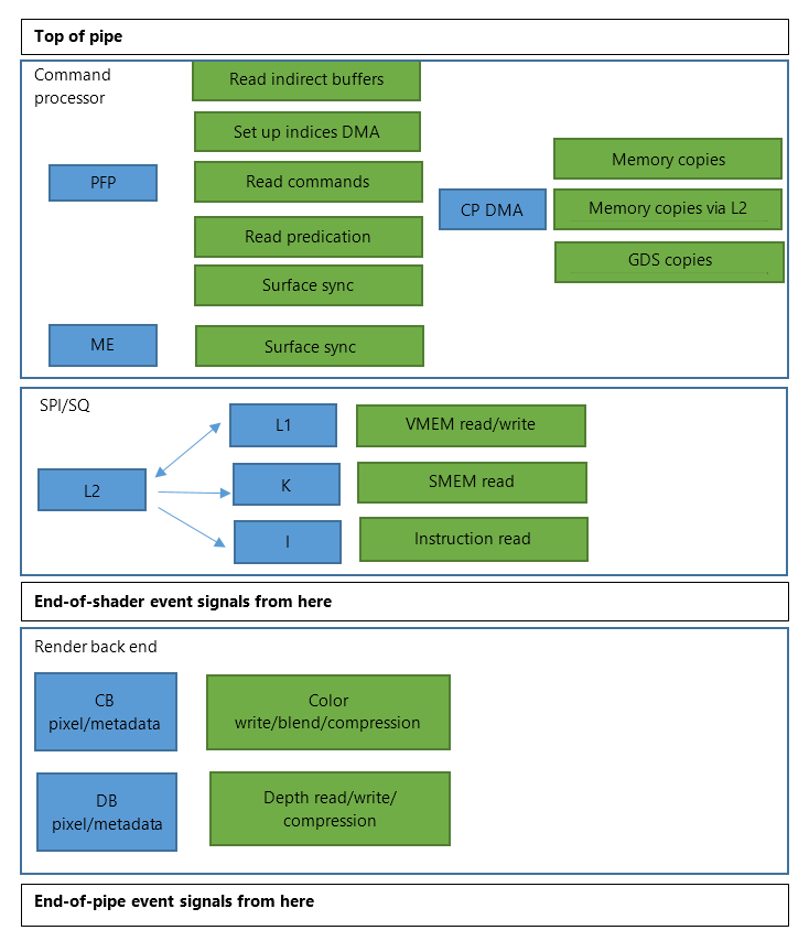
At the very top of the pipeline is the pre-fetch processor (PFP), which is the part of the command processor that reads memory for the micro-engine (ME). The PFP also kicks off the direct memory access (DMA) for the vertex geometry and tessellation (VGT) block, specifically for index buffers and indirect draw buffers.
The PFP is responsible for:
- Reading command-buffer data.
- Triggering index-buffer DMA transfers for the VGT.
- Reading indirect buffer parameters.
- Reading predication information.
- Communicating and synchronizing with the ME.
The next stage in the pipeline is the ME. The PFP and the ME, both of which are parts of the command processor, are connected by two first-in, first-out queues. Before the ME can start executing commands, all of the data must have been read from memory by the PFP.
The command processor always tries to run as far ahead of the rest of the GPU as possible and always attempts to execute command packets if it is not stalled. Synchronization at the PFP level is more expensive than synchronization at the ME level because it’s farther away from the GPU and because the mechanism for PFP-to-ME synchronization is expensive.
The command processor also contains a unit called the CP DMA, which can be used to perform generic copies of memory and global data store (GDS) through direct memory access and through the GPU L2 cache. The CP DMA can run asynchronously or synchronously with regard to the rest of the command processor packets and to itself. It can be kicked off by the PFP or the ME, but it’s used mostly from the ME.
For the purposes of this discussion, it is useful to consider the shader-execution blocks of the GPU as a monolithic block. Unless manual synchronization using shader atomics is involved, that part of the GPU pipeline is relatively straightforward when it comes to synchronization.
The fixed-function part of the GPU that executes color-buffer writes, blending, depth tests, and so forth can also be seen as a monolithic block.
Conceptually, the synchronization process through the pipeline is as follows:
- A draw packet or a dispatch command packet enters the command processor through the pre-fetch processor.
- The packet is executed by the micro-engine.
- The packet’s shader stages are executed by the shader processor input (SPI) and the sequencer (SQ).
- The fixed-function render back end (comprising the shader export block [SX], depth block [DB], and color block [CB]) finishes the non–shader related work.
End-of-pipe and end-of-shader events
Various events can be inserted into the pipeline between dispatches and draws. They all flow through the pipeline in sequence with the dispatches and draws. Two types of events are of particular interest: end-of-pipe (EOP) and end-of-shader (EOS).
Figure 1. Synchronization pipeline with arrows showing when the EOS and EOP events are signaled
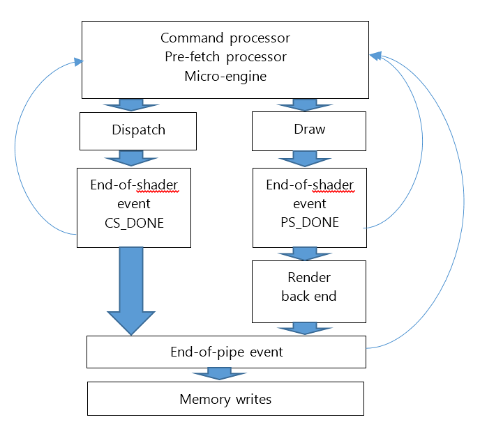
An end-of-pipe event signals back to the command processor when the shader execution and the render back-end execution are finished, but before the affected memory has finished writing. Note that EOP events treat compute and graphics work the same way.
An end-of-shader event signals back when the last wave of the draw or dispatch is retired, but before the back end finishes execution and before the memory is written. Whereas there is no compute/graphics distinction for EOP events, EOS events are different for compute and graphics. This distinction provides efficient synchronization mechanisms for different scenarios.
Pipeline barrier
A draw and dispatch pipeline barrier is sometimes needed to make sure that two draw calls or dispatches don’t run in parallel. For example, when you need to invalidate a cache between two draw calls so that the next draw call sees up-to-date data in memory and when both draw calls run at the same time, no amount of cache flushing will work; the data might be consumed before it’s produced. This is when you need to ensure that the previous draw call or dispatch is finished before the next one starts.
Figure 2. If wavefronts or back-end work of the producer overlaps with wavefronts of the consumer, a barrier is needed to ensure that they synchronize correctly.
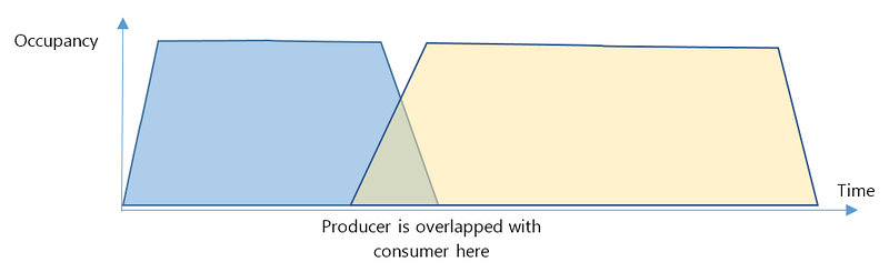
There are four mechanisms for inserting a pipeline barrier: a partial flush, an EOP fence, an EOS fence, and a surface sync. The first three are covered in this section, and surface sync is covered later in this document.
Partial flush
A partial flush is a barrier that can be inserted between two draw calls or dispatches to ensure that a previous draw call finishes before the next one starts. Upon receiving a partial-flush command, the command processor blocks packet execution until it receives a signal indicating that a vector shader (VS), pixel shader (PS), or compute shader (CS) stage has completely drained. Only one partial-flush event can be active at any time in the command processor. Note that partial-flush barriers are raised at the end-of-shader event, not when the memory has finished writing.
A partial flush can be issued in DirectX 11.x by using the GpuSendPipelinedEvent method with one of the PARTIAL_FLUSH flags.
EOS and EOP fences
A fence is a well-known synchronization primitive that can also act as a barrier. At least two packets are involved in such a barrier. The first one makes the GPU write a memory location with a value. The second makes the command processor stall until the value in memory satisfies a condition specified in the second packet. The reason a fence can be a barrier is that the value is usually written at the EOP or EOS position in the pipeline, and the wait takes place at the top of the pipe. In practice, this means that if a draw call “before the fence” is still in flight and the “wait on fence” command has been executed, all command-buffer processing is blocked until it reaches the EOP or EOS stage. The downside of using fences for pipeline barriers is the cost of at least two memory transactions, which will be at least 800 cycles or 1us.
An InsertWaitUntilIdle method is doing an EOP write with an immediate wait. That’s the heaviest pipeline barrier. The shortest this barrier can be is when the GPU is already completely idle. The WriteValueEndOfPipe method writes EOP or EOS values to a memory location, and the InsertWaitOnMemory method inserts a wait on the memory location that is equal to the given value in the packet. Note that the GPU supports multiple comparison functions, such as less than or greater than, which are exposed in the DirectX 11.x API. Also, the GPU supports fence waits in the PFP and the ME, which are also exposed in DirectX 11.x.
It is also possible to avoid synchronization by counting the number of context rolls between the producer and consumer. If eight context rolls occurred between the producer and the consumer, it’s guaranteed that the producer has retired the GPU.
Differences between PARTIAL_FLUSH, EOS fence, and EOP fence barriers
If the producer is immediately followed by the consumer, then a partial flush and an EOP fence barrier are largely equivalent. If the producer and consumer are both either draws or dispatches, the EOS fence barrier will work in the same way. In that case all three barriers would be equivalent, except that each fence must make two round trips to memory. Therefore, in cases when a producer is followed by a consumer, it makes sense to use a partial-flush barrier.
However, if there are other draw calls and dispatches between the producer and the consumer, using a partial flush could cause an unnecessary pipeline stall. Recall that a partial flush always drains the pipeline down from the specified shader stage before the next command packet is executed, as Figure 3 illustrates. The pipeline stall between the end of the second non-producer draw call and the beginning of the consumer draw call might be unnecessary.
Figure 3. Even though the producer is finished by the time the consumer starts and the two draw calls in between are independent, the partial flush introduces a stall. In this case the stall is unnecessary; the producer would never overlap with the consumer.
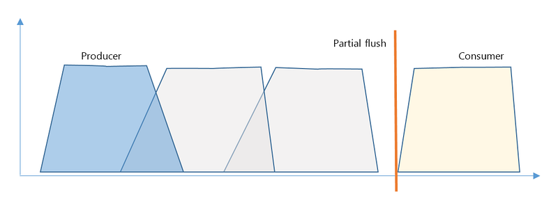
With a partial flush, it’s possible to specify whether a CS, PS, or VS stage needs draining. The InsertWaitUntilIdle method works in the same way, but it always drains all shader stages completely.
In some cases, an EOP or EOS fence is the preferred method. Because an EOP or EOS memory write is inserted immediately after the producer, the consumer simply needs to check for the corresponding fence before it starts. See Figure 4 for an illustration. This eliminates the pipeline stall that was shown in Figure 3.
Figure 4. By using fences, it’s possible to reduce or eliminate the pipeline stall between the producer and consumer, provided the draws in between are independent.
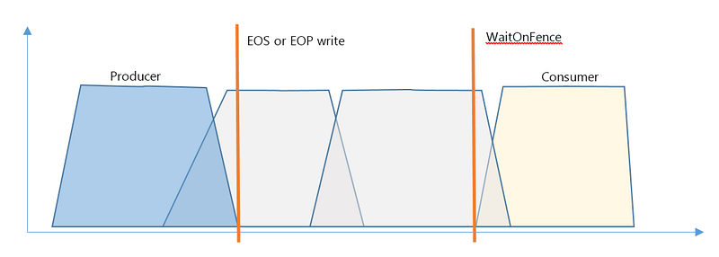
The legacy semantics driver prefers partial flushes for pipeline synchronization; doing so involves less bookkeeping. However, on fast object semantics devices, where removing or reducing pipeline stalls is important, we recommend using fences instead.
DrawA (Producer)
WriteValueEndOfPipe( myFence, 1, D3D11X_WRITE_VALUE_END_OF_PIPE_EOS ); // Assuming the value is 0 in the fence location
Draw X N
InsertWaitOnMemory ( myFence, 0, EQUAL, 1, 0xffffffff );
The difference between EOS and EOP is that EOP applies to both dispatches and draws. The result is that an EOP event will wait for all previously kicked-off draws and dispatches to complete before being signaled, while an EOS event can be made to signal separately for dispatches and draws. In some cases, when compute work runs in parallel with draws, this distinction might be important.
Pipeline synchronization doesn’t affect any GPU caches, and for a complete synchronization, cache flushes might be necessary.
Introduction to caches
There are many caches in the Xbox One GPU. Making sure that the pipeline barriers are correctly placed is the first step in synchronization. The second step is flushing and invalidating corresponding caches so that the data written by the producer is visible by the consumer.
Xbox One GPU caches usually support a writeback-and-invalidate as a single operation, and with the exception of the depth block, it’s impossible to specify the memory range of that operation. The command processor can signal cache flushes at either the top or the bottom of the pipe. All cache lines are 64 bytes.
Supported cache operations
The following table contains a list of the different caches in the Xbox One GPU along with their hardware names and supported operations. An explanation of these caches follows the table.
| Type | Writeback | Invalidate | Writeback+Invalidate | Range | |
|---|---|---|---|---|---|
| TCC (L2) | R/W | Top/Bottom | No | ||
| TCP (L1) | R/W | Top/Bottom | No | ||
| TCC VOL (L2 volatile) | R/W | Top/Bottom | Top/Bottom | No | |
| TCP VOL (L1 volatile) | R/W | Top/Bottom | Top/Bottom | No | |
| K-cache (SQC) | RO | Top | No | ||
| I-cache (SQC) | RO | Top | No | ||
| CB pixels | R/W | Bottom | Top/Bottom | No | |
| CB metadata | R/W | Bottom | No | ||
| DB pixels | R/W | Bottom | Top/Bottom | Yes | |
| DB metadata | R/W | Bottom | Yes |
- The L2 and L1 caches support flush-and-invalidate in a single operation. The L1 and the L2 caches also support a writeback operation without invalidate, but only for specially marked “volatile” cache lines. Volatile cache lines have to be marked specifically through a resource descriptor, and as of October 2014 they are not supported in the Xbox One graphics driver. The L1 and the L2 caches don’t respect flush ranges.
- Both the CB and DB caches support flush and invalidate in a single operation. The CB does not respect flush ranges.
- Only the DB supports a ranged flush-and-invalidate operation on its caches. Other blocks always invalidate the entire cache. This means that the cost of a cache flush could be significant.
No flushes are required if the data is consumed through the same cache that it has been written through. This applies to depth test and write, color blending, and unordered access view (UAV) read and write access. The only exception at present is the L1 cache, whose current policy requires it to be flushed when a producer writes through it and a consumer reads through it. See “L1 cache policies”, below, for more information.
D3D resources and caches
Different types of D3D resources use different GPU caches.
- All non-constant buffer, texture, and UAV reads and writes are done through the L1 and the L2 caches—the TCP and the TCC, respectively. In other words, all VMEM instructions go through the L1 and the L2 caches, which are read-and-write caches.
- Scalar buffer reads are done through the K$ and the L2 cache. The K$ is a read-only cache that reads through the L2. All SMEM instructions read through the K$ and the L2 cache.
- Shader instructions are read through the I$ and the L2 cache. The I$ is a read-only cache.
- Color-buffer memory access is made through a collection of CB (color block) caches. This includes reading data in for blending; the blending itself happens inside the CB unit. The CB caches include actual pixels and surface metadata, such as CMask and FMask.
- Depth-buffer memory access is made through depth block (DB) caches. This includes read and write data for depth testing, compression, and Hi-Z updates. The DB caches include actual depth pixels, depth surface metadata such as compression—PMask and planes—and Hi-Z (HTile) information.
Top-of-pipe and end-of-pipe flushes
There is a difference between a top-of-pipe and an end-of-pipe (pipelined) cache-invalidate operation. A top-of-pipe cache-invalidate operation sends the invalidate signal to the target cache immediately after the command processor reads the corresponding flush packet, no matter what work is running on the GPU at the time. This is why top-of-pipe cache flushes are usually done after a pipeline barrier stall: The producer has finished work and the consumer hasn’t started work yet.
A pipelined cache operation is executed at the end of pipe of the preceding draw call. Some flushes can be issued only as end-of-pipe events—for example, CB and DB metadata cache flushes.
Any cache flush triggers immediately but takes some time to complete. Some in-flight draw calls and dispatches can get cold caches, mid-flight. This is another reason why cache flushes might be expensive.
An end-of-pipe cache flush can be issued by using the GpuSendPipelinedEvent API in DirectX 11.x and the top-of-pipe cache flush can be issued by FlushGpuCacheRange packets. Equivalent APIs exist for asynchronous compute contexts, FlushGpuCachesBottomOfPipe and FlushGpuCachesTopOfPipe.
L1 cache policies
All VMEM operations go through the L1–L2 cache hierarchy. While the L2 cache is shared between all compute units and usually no synchronization is required to ensure VMEM instruction coherency, the L1 is instantiated per compute unit. Therefore, it’s important to understand L1 cache policies.
The L1 cache supports the following four policies:
HIT_LRU
This policy allows hits on the previous wavefront’s data, and it leaves the current wave’s data in the cache for the following waves.
HIT_EVICT
This policy allows hits on the previous wavefront’s data, and the current wave’s data is invalidated in the cache when the wave is done.
MISS_LRU
This policy doesn’t allow hits on the previous wavefront’s data, and it leaves the current wave’s data in the cache for the following waves.
MISS_EVICT
This policy doesn’t allow hits on the previous wavefront’s data, and the current wave’s data is invalidated in the cache when the wave is done.
Reads support any of the four policies, writes support MISS* variants, and atomics support only the MISS_EVICT policy.
Currently the driver is programmed to use HIT_LRU for reads and MISS_LRU for writes. Because either of these policies allow a read to hit on a previous wave’s write, the L1 cache flush might be required in some cases.
Surface sync
A surface sync is a top-of-pipe command that the driver uses both to trigger various cache flushes and invalidates. It also ensures that the write-confirms of memory writes have been received. This is called a coherency operation. Coherency operations can be performed on color blocks and depth blocks and on four arbitrary memory locations, which are used for stream-out (SO) synchronization. Both a cache-invalidate operation and a coherency operation can be specified in the same packet.
A coherency operation works by first inspecting whether a surface given by the base pointer and size parameters is now being used by active graphics contexts, then stalling the CP until those graphics contexts are finished and write-confirms for the surfaces are received. A surface sync operation involves a context roll unless it is issued between a context register setting and a draw. Note that a pipelined event is associated with a current context, so a sequence of Draw/ContextRoll/InsertPipelinedEvent/InsertSurfaceSync-that-is-waiting-on-the-pipelined-event will not work because the freshly rolled context has no draws on it.
Why might a coherency operation be required? Triggering a cache-invalidate doesn’t make that memory immediately available and visible to other GPU blocks. Sometimes it takes thousands of cycles to finish the cache-flush operation. Apart from making cache flushes really expensive, it also means that a mechanism is needed to ensure the flush is complete before starting a draw call that consumes this data.
A surface sync operation can be used as a barrier between a producer and a consumer if the producer writes through the CB or the DB. To set up such a barrier, enable flush and coherency operations on the surface sync packet at the same time. This can be accomplished as shown in the following example.
FlushGpuCacheRange(D3D11_FLUSH_ENSURE_CB0_COHERENCY | D3D11_FLUSH_TEXTURE_L2_INVALIDATE | D3D11_FLUSH_COLOR_BLOCK_INVALIDATE, renderTarget0Base, renderTarget0Size );
In DirectX 11.x, the ID3D11DeviceContextX::FlushGpuCacheRange Method uses a surface sync packet and can perform both top-of-pipe cache operations and coherency operations. You should not set the values for base address and size to zero simultaneously; sometimes this causes the DB unit to hang. Instead, use zero for the base and 0xfffffff00 for the size. These values seem to work reasonably well.
Note that flushing the FMask operation can’t be synchronized using a surface sync packet. If you need to read it back through a texture, for example, then a full GPU idle is required. This can be done using the InsertWaitUntilIdle API.
Putting it all together
With this discussion of the different GPU synchronization and coherency options in mind, how do you determine which operations will provide the optimal synchronization scenario for your title? The matrix of possible combinations is very large, which makes it impractical to take a formulaic approach. Instead, consider how synchronization works from a practical perspective. In this way, any operation can be derived from the first principles.
Ideally, synchronization should be as lightweight as possible. It is always possible to insert the heaviest GPU barrier and flush all caches at the PFP level, completely stopping the GPU and invalidating everything on it. This is good for debugging synchronization issues but is too heavy-handed to be used in production.
A possible algorithm for choosing the right synchronization:
- Identify the blocks that will be responsible for producing and consuming the data. Typical producers:
- CB: color surfaces, pixels, and metadata.
- DB: depth surfaces, pixels, and metadata.
- TCP/TCC: write-through UAVs, CopyMemoryToMemory.
- SO: stream-out (full sync is needed).
- CP: WriteValueEndOfPipe, WriteTimestampToMemory.
- CP DMA (can be using TCC): WriteGDS, some CopyResources.
- CPU: writes on the CPU.
Note For more information about improving the performance of CPU rendering, refer to the white paper entitled “Command Lists, Draw Bundles, and Deferred Contexts” available for download on the Xbox One white papers page on XGD.
Typical consumers: 1. TCP/TCC: all textures, vertex buffers, and UAV reads.- K$/TCC: all constant buffers.
- CB: color blending.
- DB: depth test.
- CP/PFP: predication buffers, vertex indices, and indirect buffers.
- CPDMA (can optionally read through the TCC): ReadGDS from memory, some CopyResources.
- Insert a pipelined (end-of-pipe) cache flush for the producer.
- GpuSendPipelinedEvent for CB, DB, and SO.
- WriteValueEndOfPipe with L1/L2 flags for the TCP/TCC.
- Use the correct pipeline barrier between the producer and the consumer.
- Partial flush
- EOS fence
- EOP fence
- Surface sync
- After the barrier’s wait operation, insert a top-of-pipe cache invalidate for the consumer. This is invariably done through a GpuCacheFlushRange operation, which invokes a surface sync.
Figure 5. Pipeline order is top to bottom. Blue blocks are GPU functional blocks. Green blocks are the operations they perform.
Examples
The following examples illustrate practical application of the synchronization operations discussed in this topic.
Synchronizing when a constant buffer is updated through the CPU
- If the CPU is using write-combined memory, and the address of the dynamic buffer hasn’t been seen in this frame, do nothing. If pointers are not 64-byte aligned, and allocation is sequential, flush the K cache.
- Issue a K and L2 cache GPU top-of-pipe flush. Because the flushes don’t respect the range, issue a flush only once per kickoff.
Synchronizing a render target that is to be used as a texture in the next draw
- Issue a producer draw call that renders into Object X as the render target through CB0.
- Issue a pipelined color-buffer pixel flush and invalidate. Method 1. Use when there are more independent draws or dispatches between producers and consumers to try to eliminate a bubble.
- Issue an EOS PS_DONE memory write.
- Before the consumer starts, insert a wait on memory.
Method 2. Similar to Method 1, but doesn’t require a memory write and read.
Surface sync operation that flushes the L2 and does a coherency check on the CB0 base address and size.
Method 3. Will introduce a pipeline bubble, so ideally use when producer and consumer are next to each other.
1. Insert a PS_PARTIAL_FLUSH.
1. Insert top-of-pipe L2 cache flush.
- Issue a consumer draw.
Synchronizing a UAV write to be used as a render target
- Issue a producer dispatch that writes into UAV X.
- Issue a pipelined L1/L2 cache flush.
- Issue an EOP fence write F (requires synchronization between a CS to PS).
- Before the consumer starts, insert a wait on fence F. (Alternatively, you can use a CS_PARTIAL_FLUSH instead of Steps 3 and 4.)
- Issue a pipelined CB and CB_META cache flush and invalidate.
- Issue a draw.
Synchronizing an indirect buffer written from a CS through a UAV
- Issue a producer dispatch that writes into UAV X.
- Issue a pipelined L1/L2 cache flush.
-
Issue an EOP fence write F (requires synchronization between a CS to PS). Method 1
Before the consumer starts, insert a wait on memory F on the PFP. The synchronization has to happen at the PFP level because it reads indirect buffers. Method 2
Use a wait on memory on the ME followed by the PFP_SYNC_TO_ME. - Issue an indirect draw.
Conclusion
Performance and correctness are always top priorities for the graphics developer. Fast object semantics contexts give a significant improvement in performance on the CPU and the GPU over the legacy semantics context. This is due partly to hazard detection and prevention in the graphics driver being disabled.
DirectX 12 also recognizes that automatic hazard detection is a difficult thing to make efficient, so it introduces the concept of “resource transition barriers” to facilitate hazard prevention.
In both cases, synchronization is now in the hands of the developer. Understanding synchronization on the Xbox One GPU, most of the time you should be able to achieve correct rendering and achieve higher synchronization performance than on legacy semantics.